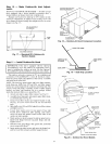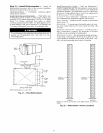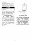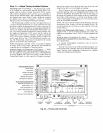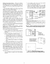
Enthalpy Sensor Jumper Settings -- There me two jumpers.
One julnper determines the mode of the enthalpy sensor. The
other jumper is not used. To access the jumpers, relnove the
4 screws holding the cover on the enthalpy sensor and then re-
move the covel: The factory settings for the jumpers are M3
and OFF.
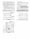
The mode jumper should be set to M3 for 4 to 20 mA
output. The factory test jumper should remain on OFF or the
enthalpy sensor will not calculate enth_dpy.
ENTHALPY SENSORS AND CONTROL -- The enthalpy
control (HH57AC077) is supplied as a field-installed accessory
to be used with the EconoMiSer2 &unper control option. The
outdoor air enthalpy sensor is part of the enthalpy control. The
separate field-installed accessory return air enthalpy sensor
(HH57AC078) is required for differential enthalpy control.
NOTE: The enthalpy control must be set to the "D" setting for
differenti_d enthalpy control to work properly.
The enthalpy control receives the indoor and return
enthalpy from the outdoor and return air enthalpy sensol_ and
provides a dry contact switch input to the PremierLink TM
controllel: Locate the controller in place of an existing econo-
mizer controller or near the actuatol: The mounting plate may
not be needed if existing bracket is used.
A closed contact indicates that outside air is preferred to the
return air An open contact indicates that the economizer
should remain at minilnuln position.
Outdoor Air Enthalpy Sensor/Enthalpy Controller
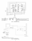
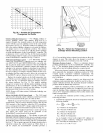
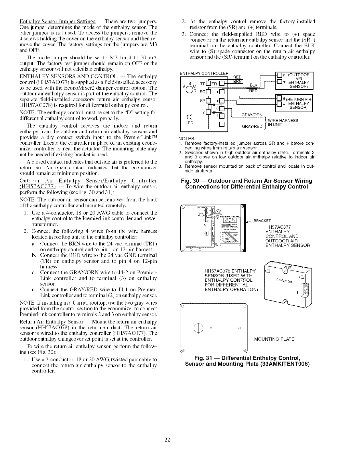
(HH57AC077) -- To wire the outdoor air enthalpy sensor,
perform the following (see Fig. 30 and 31 ):
NOTE: The outdoor air sensor can be removed froln the back
of the enth_dpy controller and mounted relnotely.
1. Use a 4-conductol, 18 or 20 AWG cable to connect the
enthalpy control to the PremierLink controller and power
tl_dnsformel:
2. Connect the following 4 wires fiom the wire h_uness
located in rooftop unit to the enthalpy controller:
a. Connect the BRN wire to the 24 vac terminal (TRI)
on enthalpy control and to pin 1 on 12-pin harness.
b. Connect the RED wire to the 24 vac GND terminal
(TR) on enthalpy sensor and to pin 4 on 12-pin
harness.
c. Connect the GRAY/ORN wire to J4-2 on Premier-
Link controller and to terminal (3) on enthalpy
sensor.
d. Connect the GRAY/RED wire to J4-1 on Premier-
Link controller and to terminal (2) on enthalpy sensol:
NOTE: If installing in a Carrier rooftop, use the two gray wires
provided fiom the control section to the economizer to connect
PrelnierLink controller to terminals 2 and 3 on enth_dpy sensol:
Return Air Enthalpy Sensor -- Mount the return-air enthalpy
sensor (HH57AC078) in the return-air duct. The return air
sensor is wired to the enthalpy controller (HH57AC077). The
outdoor enth_dpy changeover set point is set at the controller.
To wire the return air enthalpy sensol; perform the follow-
ing (see Fig. 30):
1. Use a 2-conductor, 18 or 20 AWG, twisted pair cable to
connect the return air enthalpy sensor to the enthalpy
controller.
2. At the enthalpy control remove the factory-installed
resistor fi_m the (SR) and (+) terminals.
3. Connect the field-supplied RED wire to (+) spade
connector on the return air enthalpy sensor and the (SR+)
terminal on the enthalpy controllel: Connect the BLK
wire to (S) spade connector on the return air enthalpy
sensor and the (SR) terminal on the enthalpy controller.
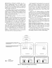
ENTHALPY CONTROLLER
RED
TR r_ TRI_"" BRN
A( C SOD+rn--
SRI-h+ID-
LED
/OUTDOOR[
AIR
ENTHALPY
BLK SENSOR)
RED
___]1 F[S (RETURN AIR I
[] + ENTHALPY
SENSOR
GRAY/ORN
LWIRE HARNESS
GRAY/RED JIN UNIT
NOTES:
1. Remove factory-installed jumper across SR and + before con-
necting wires from return air sensor,
2. Switches shown in high outdoor air enthalpy state. Terminals 2
and 3 close on low outdoor air enthalpy relative to indoor air
enthalpy.
3. Remove sensor mounted on back of control and locate in out-
side airstream.
Fig. 30 -- Outdoor and Return Air Sensor Wiring
Connections for Differential Enthalpy Control
HH57AC077
ENTHALPY
CONTROL AND
OUTDOOR AIR
ENTHALPY SENSOR
HH57AC078 ENTHALPY
SENSOR (USED WITH
ENTHALPY CONTROL
FOR DIFFERENTIAL
ENTHALPY OPERATION)
÷ ÷
MOUNTING PLATE
e,
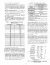
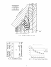
Fig. 31 -- Differential Enthalpy Control,
Sensor and Mounting Plate (33AMKITENT006)
22


