


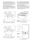

Step 8 -- Install Gas Piping -- Unit is equipped for
use with natured gas. Installation must conform with loc_d
building codes or. in the absence of loc_d codes, with the
National Fuel Gas Code, ANSI Z223.1.
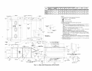
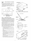
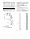
Install field-supplied manu_d gas shutoff valve with a lh-in.
NPT pressme tap for test gage connection at unit. Field gas pip-
ing must include sediment trap and union. See Fig. 13.
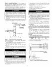
Tlansformer no. 1 is wired for 230-v unit. If 208/230-v unit
is to be run with 208-v power supply, the transformer must be
rewired as follows:
1. Remove cap fiom red (208 v) wire.
2. Remove cap from orange (230 v) spliced wire.
3. Replace orange wire with led wire.
4. Recap both wires.
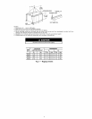
Do not pressure test gas supply while connected to unit.
Always disconnect union before servicing. Exceeding
maximum manifold pressure may cause explosion and
injury.
I IMPORTANT: Natural gas pressure at unit gas connec-
tion must not be less than 5.5 in. wg or greater than
13.5 in. wg.
Size gas-supply piping for 0.5-in. wg maximum pressure
drop. Do not use supply pipe sm_dler than unit gas connection.
MANUAL SHUTOFF
(FIELD SUPPLIED) _ FT'I
_ _ GAS
PRESSURE TAP
(1/8" NPT PLUG)
UNIT _
o& •---- SEDIMENTTRAP
Fig. 13 -- Field Gas Piping
Step 9 -- Make Electrical Connections
FIELD POWER SUPPLY- Unit is factory wiled for volt-
age shown on nameplate.
When inst_dling units, provide a disconnect per NEC (Na-
tional Electrical Code) of adequate size (Table 5).
All field wiring must comply with NEC and local
requirements.
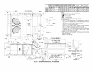
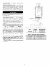
Route power ground lines through control box end panel or
unit basepan (see Fig. 4 and 5) to connections as shown on unit
wiring diagram and Fig. 14.
The correct power phasing is critical in the operation of the
scroll compressol,s. An incorrect phasing will cause the
compressor to rotate in the wrong direction. This may lead
to premature compressor failure.
The unit must be electrically grounded in accor&mce with
local codes and NEC ANSI/NFPA 70 (National Fire Pro-
tection Association) to protect against fire and electric
shock.
Field wiring must confirm to temperature limitations for
type "T" wire. All field wiring must comply with NEC and lo-
cal requirements.
Be certain unused wires ale capped. Failure to do so may
&_magethe transformers.
Operating voltage to compressor must be within voltage
range indicated on unit nameplate. On 3-phase units, voltages
between phases must be balanced within 2%.
Unit failure as a result of operation on improper line voltage
or excessive phase imbalance constitutes abuse and may cause
&Lmage to electrical components.
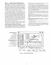
FIELD CONTROL WIRING -- Install a Carrier-approved
accessory thermostat assembly according to installation in-
structions included with accessory. Ix)cate thermostat assembly
on a solid interior wall in the conditioned space to sense aver-
age temperature.
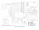
Route thermostat cable or equivalent single leads of
colored wire from subbase termimds through conduit in unit to
low-voltage connections as shown on unit label wiring diagram
and in Fig. 15.
NOTE: For wire runs up to 50 ft, use no. 18 AWG (American
Wire Gage) insulated wire (35 C minimum). For 50 to 75 ft,
use no. 16 AWG insulated wire (35 C minimum). For over
75 ft, use no. 14 AWG insulated wire (35 C minimum). All
wire larger than no. 18 AWG cannot be directly connected at
the thermostat and will require a junction box and splice at the
thermostat.
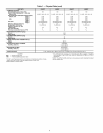
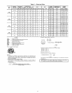
Set heat anticipator settings as follows:
VO LTAGE W1 W2
208/230,575 0.98 0.44
460 0.80 0.44
Settings may be changed slightly to provide a greater degree
of comfort for a particuku installation.
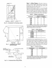
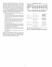
----1 TBI
II FIELD i _
i_II III I III II_
[ POWER I _
=U.l ....... SUP_PLY
z z
i
I-IN
l EQUIP GND
I
.............. ]
LEGEND
EQUIP -- Equipment
GND -- Ground
NEC -- NationalElectricalCode
TB -- Terminal Block
NOTE:The maximum wire size forTB1 is2/0.
Fig. 14- Field Power Wiring Connections
11