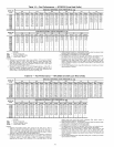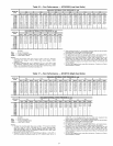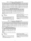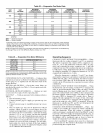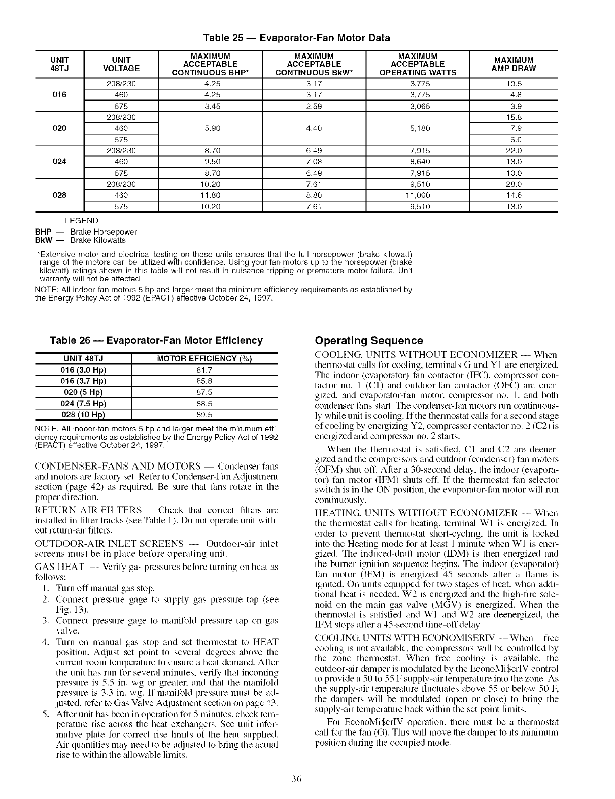
UNIT UNIT
48TJ VOLTAG E
208/230
016 460
575
208/230
020 460
575
208/230
024 460
575
208/230
028 460
575
LEGEND
BHP -- Brake Horsepower
BkW -- Brake Kilowatts
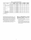
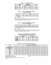
Table 25 -- Evaporator-Fan Motor Data
MAXIMUM MAXIMUM MAXIMUM
ACCEPTABLE ACCEPTABLE ACCEPTABLE
CONTINUOUS BHP* CONTINUOUS BkW* OPERATING WATTS
4.25 3.17 3,775
4.25 3.17 3,775
3.45 2.59 3,065
5.90 4.40 5,180
8.70 6.49 7,915
9.50 7.08 8,640
8.70 6.49 7,915
10.20 7.61 9,510
11.80 8.80 11,000
10.20 7.61 9,510
*Extensive motor and electrical testing on these units ensures that the full horsepower (brake kilowatt)
range of the motors can be utilized with confidence. Using your fan motors up to the horsepower (brake
kilowatt) ratings shown in this table will not result in nuisance tripping or premature motor failure. Unit
warranty will not be affected.
NOTE: All indoor-fan motors 5 hp and larger meet the minimum efficiency requirements as established by
the Energy Policy Act of 1992 (EPACT) effective October 24, 1997.
MAXIMUM
AMP DRAW
10.5
4.8
3.9
15.8
7.9
6.0
22.0
13.0
10.0
28.0
14.6
13.0
Table 26 -- Evaporator-Fan Motor Efficiency
UNIT 48TJ MOTOR EFFICIENCY (%)
016 (3.0 Hp) 81.7
016 (3.7 Hp) 65.6
020 (5 Hp) 67.5
024 (7.5 Hp) 66.5
028 (10 Hp) 69.5
NOTE: All indoor-fan motors 5 hp and larger meet the minimum effi-
ciency requirements as established by the Energy Policy Act of 1992
(EPACT) effective October 24, 1997.
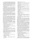
CONDENSER-FANS AND MOTORS -- Condenser fans
and motol.'s am factol T set. Refer to Condenser-Fan Adjustment
section (page 42) as required. Be sure that fans rotate in the
proper direction.
RETURN-AIR FILTERS- Check that correct filtel.s are
installed in filter tracks (see Table 1). Do not operate unit with-
out return-air filters.
OUTDOOR-AIR INLET SCREENS -- Outdoor-air inlet
screens must be in place before operating unit.
GAS HEAT -- Verify gas pressmes before turning on heat as
follows:
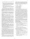
1. Turn off manual gas stop.
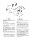
2. Connect pressure gage to supply gas pressure tap (see
Fig. 13).
3. Connect pressure gage to manifold pressure tap on gas
valve.
4. Turn on manual gas stop and set thermostat to HEAT
position. Adjust set point to several degrees above the
current room temperature to ensure a heat demand. After
the unit has mn for sevend minutes, verify that incoming
pressure is 5.5 in. wg or greater, and that the manifold
pressure is 3.3 in. wg. If manifold pressure must be ad-
justed, refer to Gas Valve Adjustment section on page 43.
5. After unit has been in operation for 5 minutes, check tem-
perature rise across the heat exchangers. See unit infor-
mative plate for correct rise limits of the heat supplied.
Air quantities may need to be adjusted to bring the actual
rise to within the zdlowable limits.
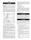
Operating Sequence
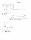
COOLING, UNITS WITHOLTT ECONOMIZER -- When
thermostat calls for cooling, terminals G and Y I are energized.
The indoor (evaporator) fan contactor (IF(?_),compressor con-
tactor no. 1 (CI) and outdoor-fan contactor (OFC) are ener-
gized, and evaporator-fan motor, compressor no. 1, and both
condenser fans stall. The condenser-fan motors mn continuous-
ly while unit is cooling. If the thermostat calls for a second stage
of cooling by energizing Y2, compressor contactor no. 2 (C2) is
energized and compressor no. 2 starts.
When the thermostat is satisfied, CI and C2 tue deener-
gized and the compressors and outdoor (condenser) fan motors
(OFM) shut off. After a 30-second delay, the indoor (evapora-
tor) fan motor (IFM) shuts off. If the thermostat fan selector
switch is in the ON position, the evaporator-fan motor will run
continuously.
HEATING. UNITS WITHOUT ECONOMIZER -- When
the thermostat calls for heating, terminal WI is energized. In
order to prevent thermostat short-cycling, the unit is locked
into the Heating mode for at least 1 minute when WI is ener-
gized. The induced-draft motor (IDM) is then energized and
the burner ignition sequence begins. The indoor (evaporator)
fan motor (IFM) is energized 45 seconds after a fame is
ignited. On units equipped for two stages of heat, when addi-
tional heat is needed, W2 is enelgized and the high-fire sole-
noid on the main gas valve (MGV) is energized. When the
thermostat is satisfied and WI and W2 are deenergized, the
IFM stops after a 45-second time-off delay.
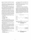
COOLING. UNITS WITH ECONOMISERIV -- When free
cooling is not available, the compressol_ will be controlled by
the zone thermostat. When free cooling is available, the
outdoor-air &unper is modulated by the EconoMiSerIV control
to provide a 50 to 55 F supply-air temperature into the zone. As
the supply-air temperature fluctuates above 55 or below 50 IF.
the &lmpers will be modulated (open or close) to bring the
supply-air temperature back within the set point limits.
For EconoMiSerIV operation, there must be a thermostat
call for the fan (G). This will move the damper to its minimum
position during the occupied mode.
36


