L1 _4
L1 -S
- (NOT BSEDI
L1-9
m
PLI _8
TO MAIN PLI _5
CONTROL /_ I
BOX PL1-6
PLI-II
1
PLI*I
PLI _R
PL1-10
(NOT USED)
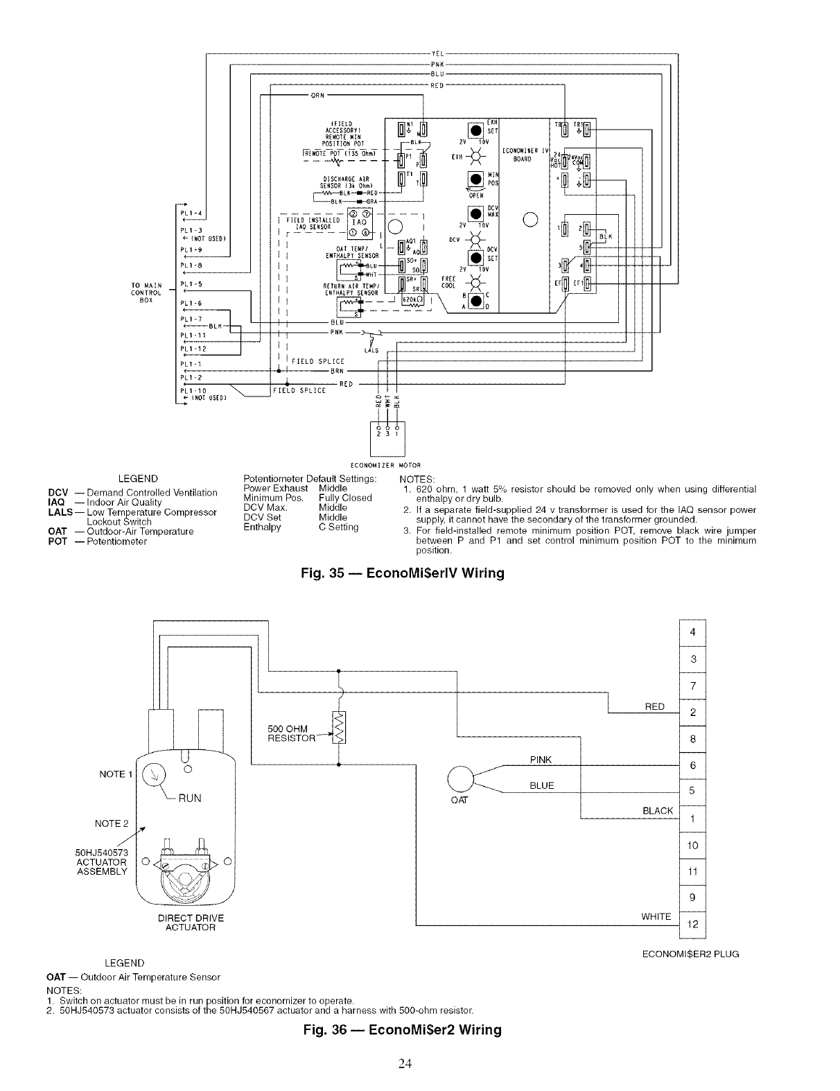
LEGEND
DCV -- Demand Controlled Ventilation
IAQ --Indoor Air Quality
LALS I Low Temperature Compressor
Lookout Switch
OAT IOutdoor_Air Temperature
POT -- Potentiometer
-- ORN
(FIE£B
ACCESSORY}
REMOTE MIN
POSITION POT
_E_T[ POT (ISS_hmT "
DISCHARGE AIR
SENSOR (Bk Ohm)
BLK_I_EO -
1 fIELD INSTALLED _IA_
F IAO SENSORI .....
I I OAT TEWPI L
I 1 ENTHALPY SENSOR
I I _Lu-
I I .T--
RETURN AIR TEHP!
1 ENTRALPY SEICSOR
IT _---
I I
1 l BLU
I l PNK--_
I I RED LALS
I IFIELD SPLICE
,_I aR.
FIELD SPLICE
ECONOMIZER MOTOR
Potentiometer Default Settings: NOTES:
Power Exhaust Middle
Minimum Pos. Fully Closed
DCV Max, Middle
DCV Set Middle
Enthalpy C Setting
YEL
PNK
-8LU
RED
EXH
I_ 1 [_ SET
BLK BV IOV
POS
OPEN
2v IBv
_so. N _ SET
_v lov
/ B C
[COBOMISER il
BOARD
©
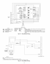
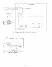
1, 620 ohm, 1 watt 5% resistor should be removed only when using differential
enthalpy or dry bulb.
2, If a separate field-supplied 24 v transformer is used for the IAQ sensor power
supply, itcannot have the secondary of the transformer grounded.
3, For field-installed remote minimum position POT, remove black wire jumper
between P and P1 and set control minimum position POT to the minimum
position,
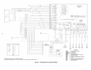
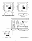
Fig. 35 -- EconoMi$erlV Wiring
NOTE 1
NOTE 2
J
50HJ540573
ACTUATOR
ASSEMBLY
/
RUN
DIRECT DRIVE
ACTUATOR
500 OHM
RESISTOR- "L_
OAT
RED
PINK
BLUE
BLACK
WHITE
4
3
7
2
8
6
5
1
10
11
9
12
ECONOMI$ER2 PLUG
LEGEND
OAT -- Outdoor Air Temperature Sensor
NOTES:
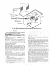
1. Switch on actuator must be in run position for economizer to operate.
2. 50HJ540573 actuator consists of the 50HJ540567 actuator and a harness with 500-ohm resistor.
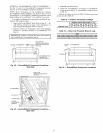
Fig. 36 -- EconoMi$er2 Wiring
24


