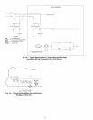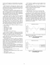
CONDENSER COiL ,
SUCTION
l DISCHARGE
F CCH
CRANKCASE
HEATER
OUTDOOR AiR
EVAPORATOR
COIL
S-LPS J
SUB COOLERCONTROL
LOW PRESSURESWITCH
TXV
SUBCOOLER /
COIL
EQUALIZER
LINE
INDOOR AIR
3-WAY
VALVE
TXV -- Thermostatic Expansion Valve
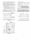
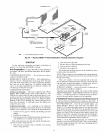
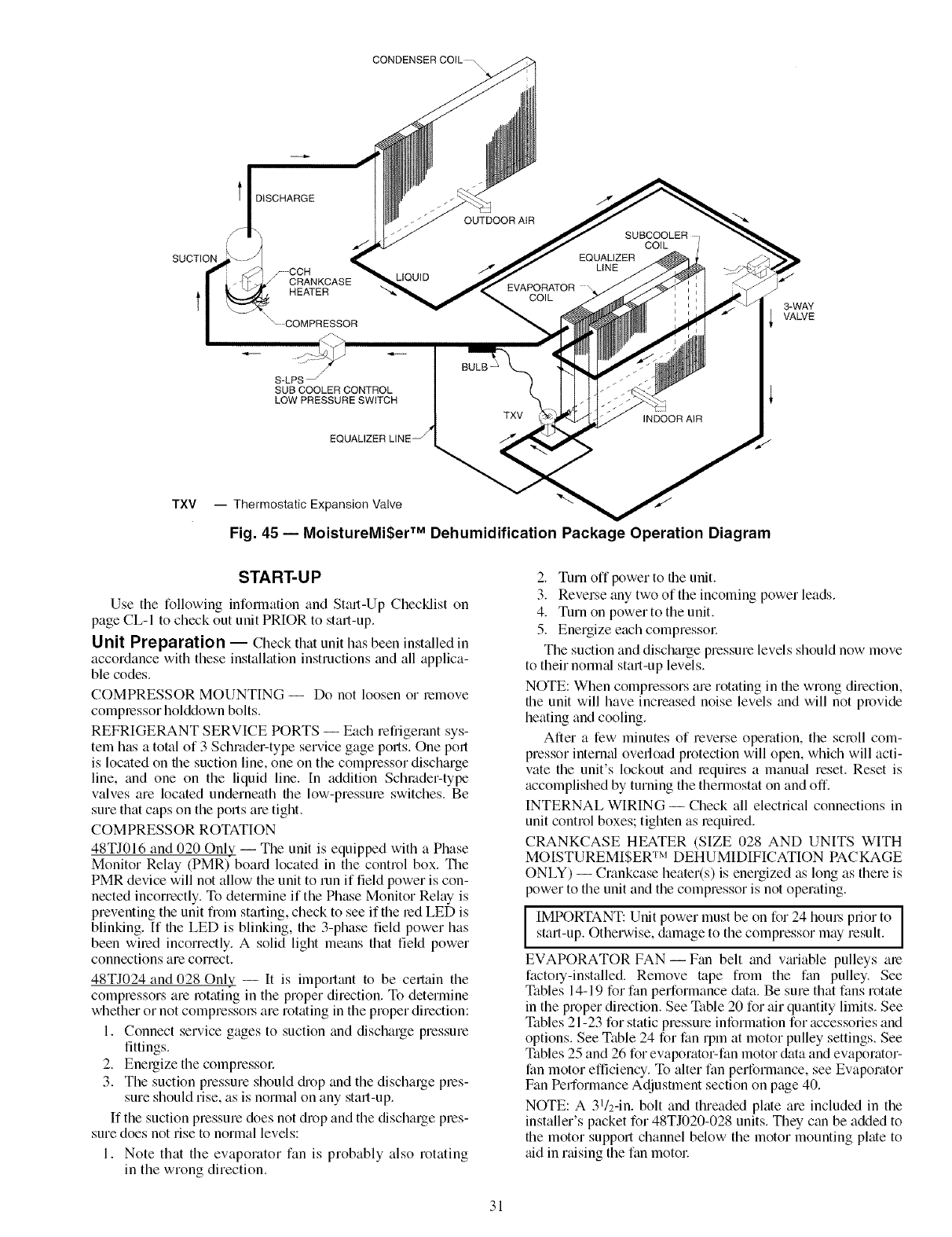
Fig. 45 -- MoistureMi$er TM Dehumidification Package Operation Diagram
START-UP
Use the following information and Start-Up Checklist on
page CL-I to check out unit PRIOR to start-up.
Unit Preparation -- Check that unit has been installed in
accordance with these installation instructions and all applica-
ble codes.
COMPRESSOR MOUNTING -- Do not loosen or remove
complessor holddown bolts.
REFRIGERANT SERVICE PORTS -- Each reh'igerant sys-
tem has a total of 3 Schrader-type service gage ports. One port
is located on the suction line, one on the compressor discharge
line, and one on the liquid line. In addition Schmder-type
valves are located underneath the low-pressme switches. Be
sure that caps on the polls are tight.
COMPRESSOR ROTATION
48TJ016 and 020 Only -- The unit is equipped with a Phase
Monitor Relay (PMR) board located in the control box. The
PMR device will not allow the unit to run if field power is con-
nected incorrectly. To determine if the Phase Monitor Relay is
preventing the unit from starting, check to see if the red LED is
blinking, ff the LED is blinking, the 3-phase field power has
been wiled incorrectly. A solid light means that field power
connections are correct.
48TJ024 and 028 Only -- It is important to be certain the
compressors are rotaing in the proper direction. To determine
whether or not compressoB are rotaing in the proper direction:
I. Connect service gages to suction and discharge pressure
fittings.
2. Energize the compressoc
3. The suction pressure should &op and the discharge pres-
sure should rise, as is normal on any start-up.
If the suction pressure does not drop and the discharge pres-
sure does not rise to normal levels:
1. Note that the evaporator fan is probably also rotating
in the wrong direction.
2. Turn off power to the unit.
3. Reverse any two of the incoming power leads.
4. Turn on power to the unit.
5. Energize each compressoc
The suction and discharge pressure levels should now move
to their normtd start-up levels.
NOTE: When compressors are rotating in the wrong direction,
the unit will have increased noise levels and will not provide
heating and cooling.
After a few minutes of reverse operation, the scroll com-
pressor intermfl overload protection will open, which will acti-
vate the unit's lockout and requires a manual reset. Reset is
accomplished by turning the thermostat on and off.
INTERNAL WIRING -- Check all electrical connections in
unit control boxes; tighten as required.
CRANKCASE HEATER (SIZE 028 AND UNITS WITH
MOISTUREMI$ER TM DEHUMIDIFICATION PACKAGE
ONLY) -- Crankcase heater(s) is energized as long as there is
power to the unit and the compressor is not operating.
I MPORTANT: Unit power must be on for 24 houB prior to Istart-up. Otherwise, &mmge to the compressor may result.
I
EVAPORATOR FAN- Fan belt and vmiable pulleys are
factory-installed. Remove tape from the fan pulley. See
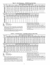
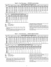
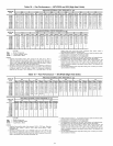
Tables 14-19 for fan performance data. Be sure that fans rotate
in the proper direction. See Table 20 for air quantity limits. See
Tables 21-23 for static pressure information for accessories and
options. See Table 24 for fan rpm tit motor pulley settings. See
Tables 25 and 26 for evaporator-fan motor data and evaporator-
fan motor efficiency. To alter fan performance, see Evaporator
Fan Perforlnance Adjustment section on page 40.
NOTE: A 31/2-in. bolt and threaded plate are included in the
installer's packet for 48TJ020-028 units. They can be added to
the motor support channel below the motor mounting plate to
aid in raising the fan motor
31


