Evaporator Fan Service and Replacement
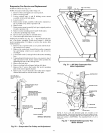
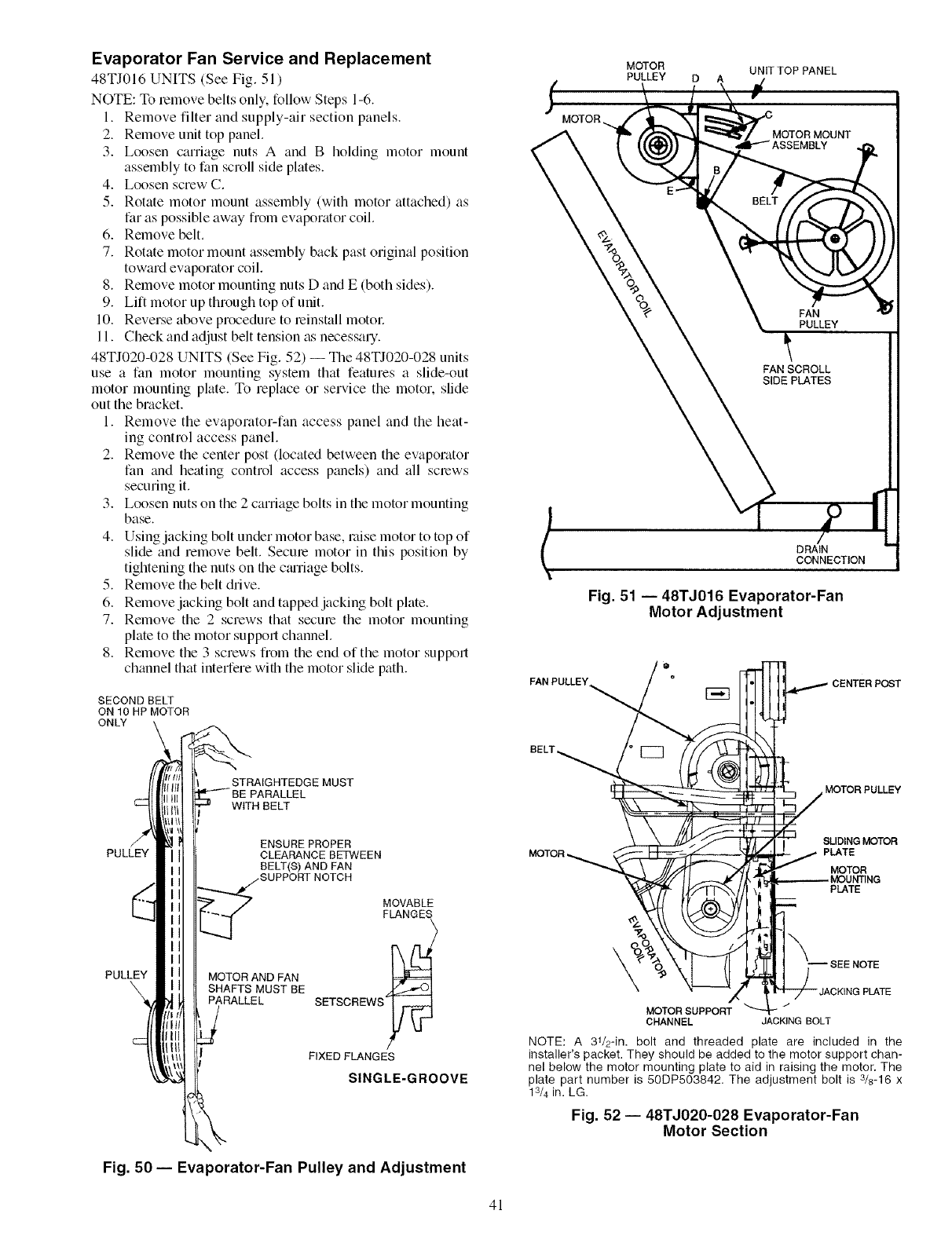
48TJ016 UNITS (See Fig. 51 )
NOTE: To lemove belts only. follow Steps 1-6.
1. Remove filter and supply-air section panels.
2. Remove unit top panel.
3. Loosen carriage nuts A and B holding motor mount
assembly to fan scroll side plates.
4. Loosen screw C.
5. Rotate motor mount assembly (with motor attached) as
far as possible away from evaporator coil.
6. Remove belt.
7. Rotate motor mount assembly back past original position
toward evaporator coil.
8. Remove motor mounting nuts D and E (both sides).
9. Lift motor up through top of unit.
10. Reverse above procedure to leinstall motol:
11. Check and adjust belt tension as necessary.
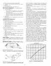
48TJ020-028 UNITS (See Fig. 52) -- The 48TJ020-028 units
use a fan motor mounting system that features a slide-out
motor mounting plate. To replace or service the motor, slide
out the bracket.
1. Remove the evaporator-fan access panel and the heat-
ing control access panel.
2. Remove the center post (located between the evaporator
fan and heating control access panels) and all screws
securing it.
3. Loosen nuts on the 2 carriage bolts in the motor mounting
base.
4. Using jacking bolt under motor base, raise motor to top of
slide and remove belt. Secure motor in this position by
tightening the nuts on the cturiage bolts.
5. Remove the belt drive.
6. Remove jacking bolt and tapped jacking bolt plate.
7. Remove the 2 screws that secure the motor mounting
plate to the motor support channel.
8. Remove the 3 screws from the end of the motor support
channel that interfere with the motor slide path.
SECOND BELT
ON 10 HP MOTOR
ONLY
j,
MOTOR
MOTOR UNIT TOP PANEL
PULLEY D A
FAN
PULLEY
FAN SCROLL
SIDE PLATES
DRAIN
CONNECTION
Fig. 51 -- 48TJ016 Evaporator-Fan
Motor Adjustment
FAN PULLEY_
BELT,
STRAIGHTEDGE MUST
PARALLEL
WITH BELT
MOTOR PULLEY
PULLEY
ENSURE PROPER
CLEARANCE BETWEEN
BELT(_ AND FAN
.SUPPORT NOTCH
PULLEY MOTOR AND FAN
\ SHAFTS MUST BE
PARALLEL
MOVABLE
FLANGES
SETSCREWS
FIXEDFLANGE
SINGLE-GROOVE
SLIDING MOTOR
PLATE
MOTOR
PLATE
\
-JACKING PLATE
MOTOR SUPPORT
CHANNEL JACKING BOLT
NOTE: A 31/2-in. bolt and threaded plate are included in the
installer's packet. They should be added to the motor support chan-
nel below the motor mounting plate to aid in raising the motor. The
plate part number is 50DP503842. The adjustment bolt is 3/8-16 x
13/4in. LG.
Fig. 52 -- 48TJ020-028 Evaporator-Fan
Motor Section
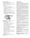
Fig. 50 -- Evaporator-Fan Pulley and Adjustment
41


