


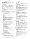
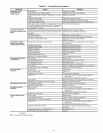

TROUBLESHOOTING
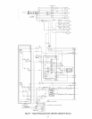
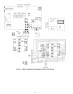
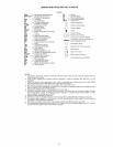
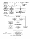
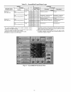
Unit Troubleshooting- Refer to Tables 27-29 and
Fig. 60.
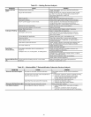
EconoMi$erlV Troubleshooting-- See Table 30
for EconoMi$erlV logic.
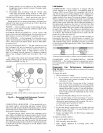
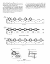
A limctional view of the EconoMiSerlV is shown in Fig. 61.
Typic_d settings, sensor ranges, and jumper positions ale also
shown. An EconoMiSerIV simulator program is available from
Ctuder to help with EconoMi$erIV training and troubleshooting.
ECONOMISERIV PREPARATION -- This procedure is
used to prepare the EconoMiSerIV for troubleshooting. No
troubleshooting or testing is done by performing the following
procedure.
NOTE: This procedure requires a 9-v battery, 1.2 kilo-ohm
resistol, and a 5.6 kilo-ohln resistor which are not supplied
with the EconoMiSerlV.
[ IMPORTANT: Be sure to record the positions of aH poten- ]tiometers before starting troubleshooting.
1. Disconnect power at TR and TRI. All LEDs should be
off. Exhaust fan contacts should be open.
2. Disconnect device at P and PI.
3. Jumper P to PI.
4. Disconnect wires at T and TI. Place 5.6 kilo-ohm resistor
across T and TI.
5. Jumper TR to 1.
6. Jumper TR to N.
7. If connected, remove sensor from termimds So and +.
Connect 1.2 kilo-ohm 4074EJM checkout resistor across
terminals So and +.
8. Put 620-ohm resistor across terminals SR and +.
9. Set minimum position, DCV set point, and exhaust
potentiometers fully CCW (counteMockwise).
10. Set DCV maximum position potentiometer fully CW
(clockwise).
11. Set enthalpy potentiometer to D.
12. Apply power (24 vac) to terminals TR and TRI.
DIFFERENTIAL ENTHALPY-- To check differential
enthalpy:
1. Make sure EconoMiSerIV prep_uation procedure has
been performed.
2. Place 620-ohm resistor across So and +.
3. Place 1.2 kilo-ohm resistor across SR and +. The Free
Cool LED should be lit.
4. Remove 620-ohm resistor across So and +. Tile Free
Cool LED should turn off.
5. Return EconoMiSerIV settings and wiring to normal
after completing troubleshooting.
SINGLE ENTHALPY -- To check single enthalpy:
1. Make sure EconoMiSerIV prepmation procedure has
been performed.
2. Set the enthalpy potentiometer to A (fully CCW). The
Free Cool LED should be lit.
3. Set the enth_flpy potentiometer to D (fully CW). The Free
Cool LED should turn off.
4. Return EconoMiSerlV settings and wiring to normal
after completing troubleshooting.
DCV (Demand Controlled Ventilation) AND POWER
EXHAUST -- To check DCV and Power Exhaust:
1. Make sure EconoMiSerIV prepmation procedure has
been performed.
2. Ensure terminals AQ and AQI _ue open. The LED for
both DCV and Exhaust should be off. The actuator
should be fldly closed.
3. Connect a 9-v battery to AQ (positive node) and AQI
(negative node). The LED for both DCV and Exhaust
should turn on. The actuator should &ive to between 90
and 95% open.
4. Turn the Exhaust potentiometer CW until the Exhaust
LED turns off. The LED should turn off when the
potentiometer is approximately 90%. The actuator should
remain in position.
5. Turn the DCV set point potentiometer CW until the DCV
LED turns off. The DCV LED should turn off when the
potentiometer is approximately 9-v. Tile actuator should
drive fully closed.
6. Turn the DCV and Exhaust potentiometers CCW until
the Exhaust LED turns on. The exhaust contacts will
close 30 to 120 seconds after the Exhaust LED turns on.
7. Return EconoMi$erIV settings and wiring to normal
after completing troubleshooting.
DCV MINIMUM AND MAXIMUM POSITION -- To check
the DCV minimum and maximum position:
1. Make sure EconoMiSerIV preparation procedure has
been perforlned.
2. Connect a 9-v battery to AQ (positive node) and AQI
(negative node). The DCV LED should turn on. The
actuator should drive to between 90 and 95% open.
3. Turn the DCV Maximum Position potentiometer to mid-
point. The actuator should drive to between 20 and 80%
open.
4. Turn the DCV Maximum Position potentiometer to lidly
CCW. The actuator should drive fully closed.
5. Turn the Minimum Position potentiometer to midpoint.
The actuator should drive to between 20 and 80% open.
6. Turn the Minimum Position Potentiometer lully CW. The
actuator should drive fully open.
7. Remove the jumper from TR and N. The actuator should
drive fully closed.
8. Return EconoMiSerIV settings and wiring to norm¢fl
after completing troubleshooting.
SUPPLY-AIR [NPUT -- To check supply-air input:
1. Make sure EconoMiSerIV preparation procedure has
been performed.
2. Set the Enthalpy potentiometer to A. The Free Cool LED
turns on. The actuator should drive to between 20 and
80% open.
3. Remove the 5.6 kilo-ohm lesistor and jumper T to TI.
The actuator should drive fidly open.
4. Remove the jumper across T and TI. The actuator should
drive fully closed.
5. Return EconoMiSerlV settings and wiring to normal
after completing troubleshooting.
ECONOMISER IV TROUBLESHOOTING COMPLE-
TION -- Tiffs procedure is used to return the EconoMiSerIV
to operation. No troubleshooting or testing is done by perform-
ing the following procedure.
1. Disconnect power at TR and TRI.
2. Set enthalpy potentiometer to previous setting.
3. Set DCV maximum position potentiometer to previous
setting.
4. Set minimum position, DCV set point, and exhaust
potentiometers to previous settings.
5. Remove 620-ohm resistor fix_m terminals SR and +.
6. Remove 1.2 kilo-ohln checkout resistor from terminals So
and +. If used, reconnect sensor fix_mterminals So and +.
7. Remove jumper from TR to N.
8. Remove jumper from TR to 1.
9. Remove 5.6 kilo-ohm resistor from T and TI. Reconnect
wires at T and TI.
10. Remove jumper from P to PI. Reconnect device at P and
PI.
11. Apply power (24 vac) to termimds TR and TRI.
48