


12 en | Connections CTFID
F.01U.141.545 | 3.09 | 2009.10 User’s Manual Bosch Security Systems, Inc.
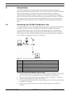
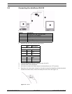
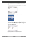
Connecting the VP-RS2BLNX Configuration Tool to Your PC
1. Pin 1 and 2 of the terminal block are for the connections for the external power supply
not provided. The external power supply should be either 12-28 VAC (50/60 Hz) or 12-
40 VDC (polarity independent). Galvanically insulated from video, RS-232 ground and
encasing.
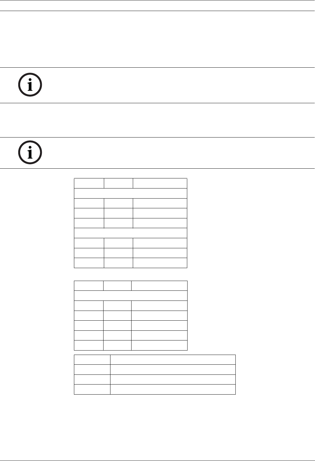
2. Connect a cable between the terminal block of the VP-RS2BLNX Configuration Tool to
the serial port on the computer. Refer to the pin out table below for the proper
connections.
-or-
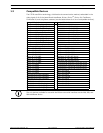
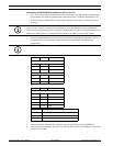
Table 3.1 Mode and Baud Rate Selections
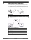
3. Connect the coax from the Bilinx device to one of the BNCs on the VP-RS2BLNX.
4. Connect a second coaxial cable from the looping output of the VP-RS2BLNX to the input
of the CCTV monitor.
NOTICE! The Serial to Bilinx converter interface shall be supplied by a self-limited power
source of less than 15 VA. Reinforced insulation is provided between input and output by
safety transformer and distances on the PCB. USA/Canada: The Serial to Bilinx converter is a
product for INDOOR use. It is intended for use with a UL-listed Class 2 power supply.
NOTICE! The VP-RS2BLNX can operate in RS-232 or RS-485 mode.
Pin # Description
PC DB9
2RxD
3TxD
5GnD
VP-RS2BLNX terminal block
Pin 3 GND
Pin 4 TxD
Pin 5 RxD
Pin # Description
VP-RS2BLNX terminal block
Pin 6 Tx/Rx+ (B)
Pin 7 Tx/Rx- (A)
Pin 8 Do not connect
Pin 9 Do not connect
Pin 10 GND
Dip switch Description
8 On: RS-485, Off: RS-232
7 RS-232 baud rate (On: 4800, Off: 9600 Bps)
7-1 RS-485 address (0 to 127)