


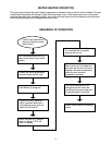
9
COMBUSTION AIR AND VENT SYSTEM REQUIREMENTS
Vent Connectors:
1. Type B, Double wall, U.L. Listed Vent Pipe.
2. Single wall Vent Pipe.
Maintain the manufacturer’s specifi ed minimum
clearance from combustible materials when using
type B double wall vent pipe.
Vent connectors made of type B, double wall
vent pipe material may pass through walls or
partitions constructed of combustible material if
the minimum listed clearance is maintained.
Maintain a one inch minimum clearance from all
combustible materials when using single wall vent
pipe.
IMPORTANT: Single wall vent pipe cannot be
used for water heaters located in attics and may
not pass through attic spaces, crawl spaces or
any confi ned or inaccessible location. A single wall
metal vent connector cannot pass through any
interior wall.
When installing a vent connector, please note the
following
• Install the vent connector avoiding
unnecessary bends, which create resistance
to the flow of vent gases.
• Install without dips or sags with an upward
slope of at least 1/4-inch per foot.
• Joints must be fastened by sheet metal
screws or other approved means. It must be
supported to maintain clearances and prevent
separation of joints and damage.
• The length of the vent connector cannot
exceed 75% of the vertical vent height.
• The vent connector must be accessible for
cleaning, inspection, and replacement.
• Vent connectors cannot pass through any
ceiling, floor, firewall, or fire partition.
• It is recommended (but not mandatory) that
a minimum 12 inches of vertical vent pipe be
installed on the draft hood prior to any elbow
in the vent system.
IMPORTANT: Existing vent systems must be
inspected for obstructions, corrosion, and proper
installation.
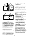
Chimney Connection: IMPORTANT: Before
connecting a gas vent to a chimney, make sure
the chimney passageway is clear and free of
obstructions. The chimney must be cleaned if
previously used for venting solid fuel appliances
or fireplaces. Also consult local and state codes
for proper chimney sizing and application or, in the
absence of local and state codes, the “National Fuel
Gas Code”, ANSI Z223.1(NFPA 54)-current edition.
• The connector must be installed above the
extreme bottom of the chimney to prevent
potentially blocking the flue gases.
Figure 6.
Figure 7.
Vent Pipe System: This water heater must be
properly vented for the removal of exhaust gases
to the outside atmosphere. Correct installation of
the vent pipe system is mandatory for the proper
and effi cient operation of this water heater and is
an important factor in the life of the unit.
The vent pipe must be installed according to all
local and state codes or, in the absence of local
and state codes, the “National Fuel Gas Code”,
ANSI Z223.1(NFPA 54)-current edition. The vent
pipe installation must not be obstructed so as
to prevent the removal of exhaust gases to the
outside atmosphere.
U.L. recognized fuel gas and carbon monoxide
(CO) detectors are recommended in all
applications and should be installed using the
manufacturer’s instructions and local codes, rules,
or regulations.
Vent Pipe Size: It is important that you follow the
guidelines in these instructions for sizing a vent
pipe system. If a transition to a larger vent size is
required, the vent transition connection must be
made at the draft hood outlet. DO NOT reduce
the vent size to less than the draft hood outlet
diameter.
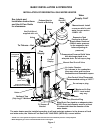
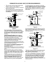
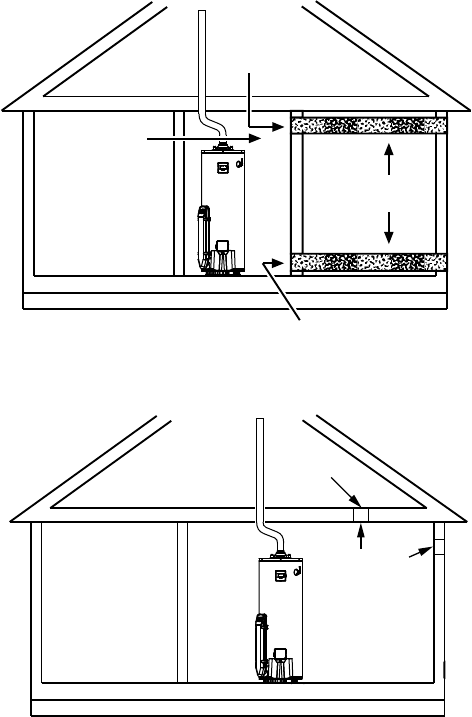
1 SQ. INCH PER
2000 BTUH
100 SQ. INCH
MINIMUM (EACH)
CONFINED
SPACE
1 SQ. INCH PER
2000 BTUH 100 SQ. INCH
MINIMUM (EACH)
INLET
OUTLET
OUTDOOR
AIR DUCTS
ALL AIR FROM OUTDOORS USING HORIZONTAL DUCTS
ALTERNATIVE
OPENING
LOCATION
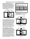
1 SQ. INCH
PER 3000 BTUH
100 SQ. INCH
MINIMUM (EACH)
CONFINED
SPACE
ALL AIR FROM OUTDOORS - USING A SINGLE PERMANENT OPENING