21
6.
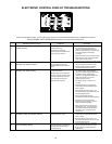
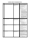
“P-SW”, “OPEN”, and “CLEAN SCREEN” Flashing
The air pressure switch contacts
remain open longer than 11
seconds after the combustion fan
is energized.
1. Clean the screen on the combustion air
intake chamber. Turn the power “OFF” for
10 to 20 seconds then “ON” again to clear
2. Ensure the pressure switch sensing tube
is in good condition and securely
connected at both ends.
3. Ensure the inner door to the combustion
chamber is secure and the gasket is
properly sealing.
4. Check operation of the air intake chamber
A. Turn o power to the water heater.
B. Remove the tubing from the pressure
switch and the wires from both
7.
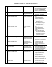
“P-SW” and “SHORT” Flashing
The air pressure switch contacts
remain closed for more than 5
seconds when they should be
open.
1. Turn o power to the water heater.
2. Locate the pressure switch wiring –
ensure pressure switch wiring is correct
and not jumped.
3. Remove wires to both terminals on
pressure switch.
4. Check pressure switch contacts with an
ohmmeter for continuity.
A. If pressure switch contacts show
continuity (closed circuit) replace
the pressure switch.
B. If pressure switch contacts show
open circuit and all wiring is correct
– replace the lower control.
8.
“IGN” Flashing
Open ignitor circuit
1. Check all wiring to the hot surface ignitor.
2. Check the 3 pin Molex ignitor assembly
plug and receptacle on the lower control
for a good connection. Repair or replace
parts if necessary.
3. Check resistance of the ignitor with an
ohmmeter on the ignitor assembly plug.
Replace ignitor if resistance is not within
1.72 and 2.40 ohms.
4. If above checks are good – turn o
power for 10 seconds and then back on.
If this error code will not clear and the
ignitor resistance is within specications
– replace the lo
wer control.
9.
“FV-SENSE” Flashing
Flammable Vapor Sensor has
detected the presence of
ammable vapors and is in lockout
1. Do not touch any electrical switch, do not use
any phone in the building and do not try to
CONTROL DISPLAY STATUS
PROBLEM
SOLUTION
the error code. If the problem persists:
fan and pressure switch.
terminals of the pressure switch.
C. Connect a digital manometer to the
open end of the tubing from the air
intake chamber. Turn on the power to
the water heater and when the fan turns
on, measure the pressure reading in the
tubing. If the pressure reading reaches
the .22” WC make point of the pressure
switch, turn o power to the water
heater and reconnect tubing to the
pressure switch. If pressure reading does
not reach the .22” WC make point, check
the system and tubing for restrictions
and cleanliness.
D. Attach leads of ohmmeter or continuity
tester to the terminals of the pressure
switch. Turn on power to the water
heater and when the air intake fan
comes on, check for continuity across
the pressure switch contacts. If switch
contacts remain open (no continuity)
while the fan is in operation - replace
the pressure switch.
light any appliance.
2. Smell around the water heater to ensure there
are no gas leaks at the gas control valve or in
the supply gas line or for any other type of
ammable vapors in the area.
3. Carefully inspect the area surrounding the
water heater for any substances such as gas-
oline, paint, paint thinners, varnish, or cleaners
that could emit ammable vapors. Remove
anything that can potentially emit ammable
vapors from the area and store it properly in a
dierent location.
~ continued next page ~
CONTROL DISPLAY TROUBLESHOOTING


