


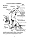
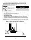

11
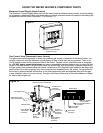
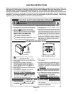
KNOW THE WATER HEATER’S COMPONENT PARTS
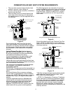
Figure 11.
Electronic Control Display (Upper Control)
The Electronic Control Display panel used on this water heater provides an easy-to-read, eye level display
for temperature adjustment, fault code diagnostics and recall, powered anode rod operation and setting the
temperature scale for either Fahrenheit (°F) or Celsius (°C).
Gas Control Valve/Thermostat (Lower Control)
The gas control valve/thermostat is where the incoming gas supply is connected to the water heater. It is
used in conjunction with the electronic control display to start or stop main burner operation. There is an
On/Off switch located on the right-hand side of the control. The gas control valve/thermostat is energized
by a 24 VAC power supply transformer and uses a temperature sensing probe to open or close the flow
of gas to the main burner. The gas control valve has an inlet filter built into its body to prevent impurities in
the gas system from contaminating the internal valves and a LED diagnostic light located in the lower right
hand corner of the valve to display any micro-computer fault experienced by the control. On the bottom of
the control is where electrical connections to the other component parts are attached along with the gas
supply (manifold tube) to the main burner. The gas control/valve thermostat of this water heater is suitable
for use on Natural gas only.
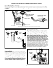
Manifold Tube
Control Display,
Anode Rod
Connector
Pressure
Switch / Fan,
FV Sensor
Connector
Power Supply
Transformer
Connector
Igniter/Flame
Sense
Connector
Gas Control Valve/ Thermostat
Temperature Probe
/High Limit Probe
Gas Supply- Inlet
Bottom View
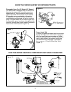
8 Pin Systems
Connector
5 Pin Communications
Connector
3 Pin Ignitor
Connector
2 Pin Power
Connector
1
2
3
4
1
2
3
4
On/Off Switch
located on
the right side.
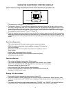
Figure 12.
Electronic Control Display
(Upper Control)