


35
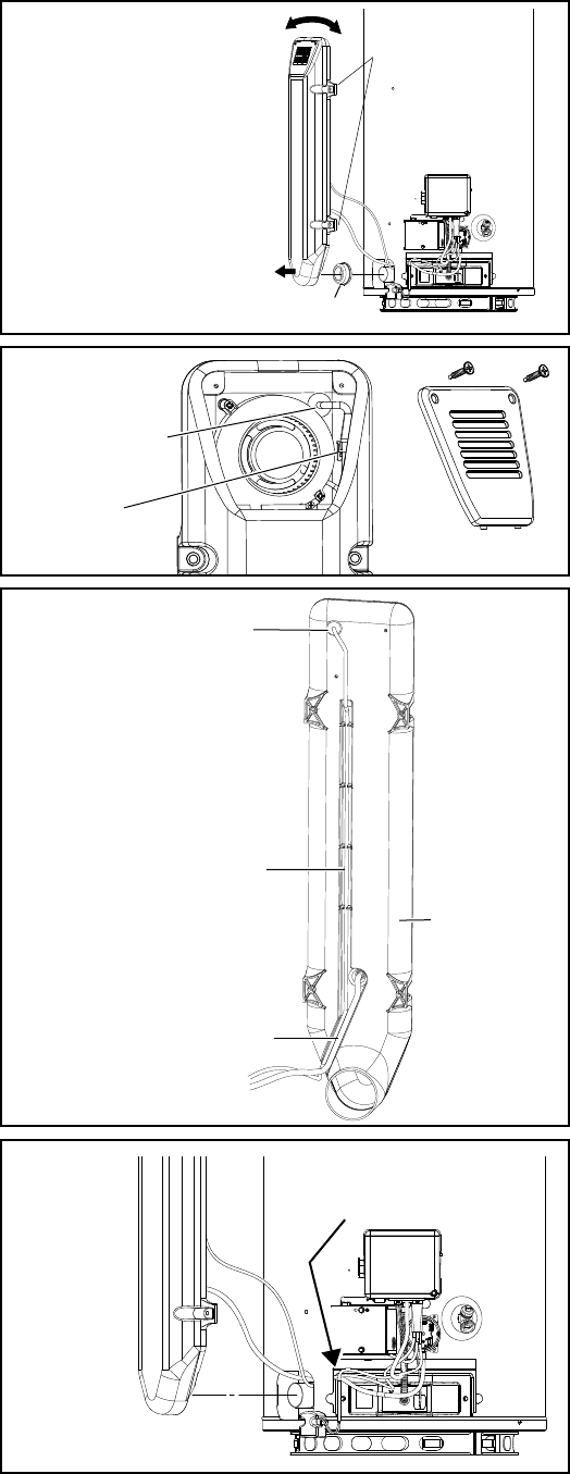
Replacing the Wiring Harness:
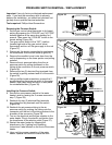
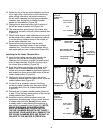
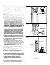
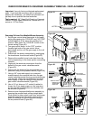
13. Locate the male to female electrical connection
with close pin lock on wiring harness (located on
the right side of fan) (Figure 62).
14. To separate the electrical connection of the fan
and wiring harness: press down on the back
portion of the close pin lock of the electrical
connection while pulling the connection in the
opposite directions.
15. The wire harness goes through the rubber wire
protector in the back of the air intake chamber box
(Figure 62).
16. Reach inside the air intake chamber box and push
on the center of the rubber wire protector pushing
it and the wiring harness wires to the outside of
the air intake chamber box (Figure 62).
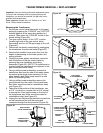
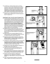
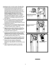
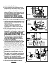
17. Remove the wiring harness from the wire
channeling in the back center of the air intake
chamber box (Figure 63).
18. The old wiring harness can now be discarded.
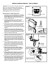
Installing the New Wiring Harness:
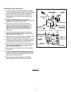
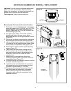
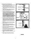
19. Route the multi-lead portion of the new wiring
harness through the opening at the bottom of the
water heater’s jacket (Figure 64).
20. Insert the fan wiring harness wire through the
back and into the fan box compartment by
threading the connector through the opening and
insert in approximately 6 inches of wiring (up to
the rubber wire protector) (Figure 62).
21. Push the rubber wire protector into place in the
back of the air intake chamber box (Note: The
rubber wire protector must be positioned properly
and locked into place around both sides of the air
intake chamber box) (Figure 63).
22. Position the wiring harness wire in the wiring
channeling molded down the back center of the air
intake chamber box (Figure 63).
23. Plug the electrical connections of the fan into the
wiring harness: Align the electrical connections in
such a position as to ensure the locking portions
of the connections are on the same side. Gently
push the electrical connectors together until the
snap lock on the wiring harness engages the
angular lock on the fan connector. Do Not use
undue force in pushing these connectors together
(Figure 62). (Note: Connectors are designed in
such a manner if the connection is not properly
aligned they will not lock together).
24. Route the wiring inside the fan box to the outer
edge of the fan in such a manner to ensure it will
not be pinched or damaged upon installation of
the air intake screen (Figure 62).
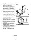
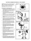
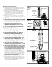
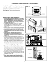
Figure 61.
AIR INTAKE
CHAMBER BOX
REMOVAL
CHAMBER GASKET
ROTATE FROM
LEFT TO RIGHT
AND
PULL OUTWARD
REMOVE SCREWS
RUBBER WIRE
PROTECTOR
Figure 62.
AIR INTAKE
CHAMBER SCREEN.
ELECTRICAL
CONNECTION
Figure 64.
ROUTE WIRING HARNESS
THROUGH OPENING AT
BOTTOM OF JACKET.
Figure 63.
RUBBER WIRE
PROTECTOR
WIRE HARNESS INSIDE
WIRE CHANNELING
AIR PRESSURE TUBING
CONNECTION
REAR SIDE OF
THE AIR INTAKE
CHAMBER BOX