


50
GAS CONTROL VALVE/THERMOSTAT REMOVAL / REPLACEMENT
Important: Use only factory authorized replacement
parts. If you lack the necessary skills to properly
perform the installation, you should not proceed, but
get help from a qualified service technician.
Tools required: 3/4” Open-End Wrench or Crescent
Wrench, Phillips Head Screwdriver, a short length of
1/2” threaded Pipe.
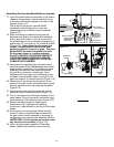
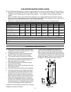
Removing the Gas Control Valve/Thermostat:
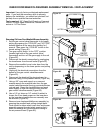
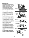
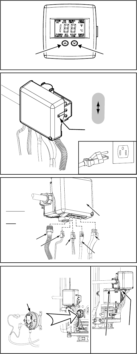
1. Set the gas control valve/thermostat to its lowest
setting by pressing the “COOLER” and “HOTTER”
buttons together at the same time holding for 1
second. Then press the “COOLER” button to the
lowest setting (Figure 112).
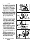
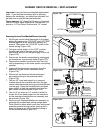
2. Turn gas control switch to the “OFF” position
(located right side of the gas control valve/
thermostat) and turn off the gas supply to the unit
(Figure 113).
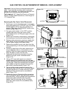
3. Disconnect the electric connection by unplugging
the transformer from the wall outlet (Figure 113).
4. Release water pressure by opening a nearby hot
water faucet, let run until water is cool to touch.
Turn off water supply to the water heater.
5. Remove the manifold cover/ outer door from the
unit by depressing on the lower portion and pulling
outward.
6. Connect a drain hose to the drain valve and run
it to an adequate drain or to the exterior of the
building. Open the water heater drain valve and
allow the water to drain from the tank.
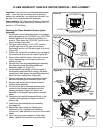
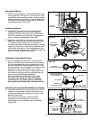
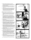
7. Unplug all the electrical connections from the
bottom of the gas control valve/thermostat
(Figure 114).
8. Using a 3/4” open end wrench or a crescent
wrench remove the manifold tube from the gas
control valve/thermostat (turning counterclockwise
-natural gas). Grasp the manifold tube and push
down slightly to free the manifold tube from the
gas control valve/thermostat (Figure 114).
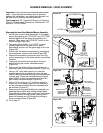
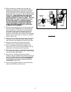
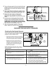
9. Using a phillips head screwdriver remove the
transformer box from the front of the water heater
by removing the one (1) screw at the top of the
transformer box (save screw for reinstallation
later) (Figure 115).
10. Disconnect the two (2) electrical flag connectors
from the pressure switch, also disconnect the air
pressure tubing. Using a phillips head screwdriver
remove the pressure switch from the water
heater’s front by removing the two (2) screws
securing it (save screws for reinstallation later)
(Figure 115).
g
COOLER
HOTTER
Electronic Control Display
Figure 112.
ON/OFF
SWITCH
ON
OFF
Figure 113.
UNPLUGGED
IMPORTANT:
WHEN BRUSHING ON AN
APPROVED NONCORROSIVE
LEAK DETECTION SOLUTION,
DO NOT SPLASH SOLUTION
ONTO ELECTRICAL CON-
NECTIONS.
IGNITER/
FLAME
SENSE
CONNECTOR
MANIFOLD TUBE
POWER SUPPLY
TRANSFORMER
CONNECTOR
PRESSURE
SWITCH/FAN,
FV SENSOR
CONNECTOR
DISPLAY, ANODE
ROD CONNECTOR
GAS CONTROL
VALVE/THERMOSTAT
Figure 114.
Figure 115.
PRESSURE
SWITCH
MANIFOLD
TUBE
SCREW AT
TRANSFORMER
BOX