


19
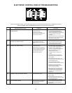
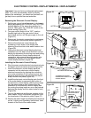
USING THE ELECTRONIC CONTROL DISPLAY
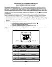
Reviewing Fault Codes:
1. Press the red up arrow button one time.
2. The display will show either E0 or E1.
3. If E0 is shown, there are no faults. By pressing the up arrow button again the display will exit the Field
Service mode, or the control will exit automatically after no button is pressed for five (5) seconds.
4. If E1 is shown, the control will flash the icons of the most recent fault.
5. Pressing the red up arrow button again will shown how many days ago the fault occurred and continue to
flash the corresponding fault icons.
6. Interpreting the day of the fault occurrence is as follows...00 would be today, 01 would be yesterday, up to
14 which would be 14 or more days ago.
7. Continuing to press the up arrow button will scroll through all of the eight (8) most recent faults, if they exist,
and its days ago of occurrence.
8. After the last fault is reached the display will return to the first fault (E1) to allow for the faults to be reviewed
again.
Exiting Field Service Mode:
• There are three (3) methods to exit the Field Service Mode, Manual, Manual and Clear, and Timed Exit.
1. Manual exit is accomplished by pressing both the red up arrow and the blue down arrow buttons for
one (1) second, but less than five (5) seconds while in the Field Service Mode, or by pressing the red
up arrow button one (1) time after the “E0” is displayed during fault review while in the Field Service
Mode. These methods will return the control to the standard operating mode and retain any fault codes
stored in memory.
2. Manual exit and fault clear is accomplished by pressing the red up arrow and the blue down arrow
buttons for five (5) seconds while in the Field Service Mode. This method will return the control to the
standard operating mode and at the end of the five (5) seconds clear all faults stored in memory
and initiate a software reset indicated by all the LCD segments coming on for five (5) seconds. The
temperature setting and scale, etc. will not be altered using this method of exit.
3. Timed exit will occur while in the Field Service Mode if the control detects no button presses for a
period exceeding five (5) minutes. The control will automatically return to the normal operating mode
and keep all fault data retained in memory.
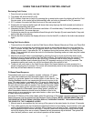
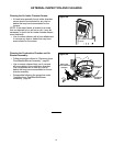
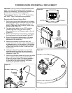
FV-Sense Reset Sequence:
Flammable liquids (such as gasoline, solvents, adhesives, LP gases,
etc.) and other substances emit flammable vapors which can be
ignited by a gas water heater’s hot surface igniter or main burner. The
resulting flashback and fire can cause serious burns to anyone in the
area. This water heater is equipped with a FV sensor for detecting the
presence of flammable vapors. When the sensor detects those vapors,
the unit will shut down and not operate. Even though this water heater
is a flammable vapors ignition resistant water heater and designed to
reduce the chances of flammable vapors being ignited, gasoline and
other flammable substances should never be stored or used in the
same vicinity or area containing a gas water heater or other open flame
or spark producing appliance.
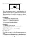
Should the FV-Sensor of this water heater detect the presence of flammable vapors the following FV-Sense
Reset Sequence must be entered into the Electronic Control Display. NOTE:
“BEFORE RESETTING THE
FVIR SENSE IN THE ELECTRONIC CONTROL DISPLAY, THOROUGHLY INSPECT THE AREA AND REMOVE
THE SOURCE OF THE FLAMMABLE VAPORS”
.
1. Manual reset is accomplished by first turning off the power to the water heater for at least 10 seconds.
2. Then, while pressing the two temperature adjustment buttons on the display, turn the switch on the gas
control valve/thermostat to the on position. All the display icons will start to flash. Temporarily release
both temperature adjust buttons and within 2 seconds, press both temperatures adjust buttons again
until all the display icons are on steady. Release the two temperature adjust buttons. The system will
clear the fault, perform a reset, and normal operation will be restored.
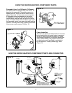
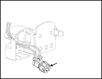
FV Sensor
Figure 23.