


32
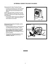
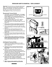
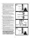
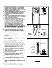
14. Rotate the top of the air intake chamber box from
left to right (only a few inches in both directions)
while pulling outward at the bottom removing
the air intake chamber box from the combustion
chamber pipe saving the air intake chamber
gasket for reinstallation (Figure 49).
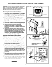
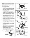
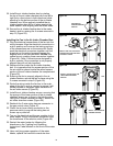
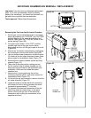
15. Unplug the air pressure tubing from the back of
the old air intake chamber box (Figure 50).
16. The wire harness goes through the rubber wire
protector in the back of the air intake chamber box
(Figure 50).
17. Reach inside the air intake chamber box and push
on the center of the rubber wire protector pushing
it and the wiring harness wires to the outside of
the air intake chamber box.
18. Remove the wiring harness from the wire
channeling in the back center of the air intake
chamber box. The old air intake chamber box is
now separated and can be discarded (Figure 50).
Installing the Air Intake Chamber Box:
19. Insert the fan wiring harness wire through the
back and into the fan box compartment by
threading the connector through the opening and
insert in approximately 6 inches of wiring (up to
the rubber wire protector) (Figure 50).
20. Push the rubber wire protector into place in the
back of the air intake chamber box (Note: the
rubber wire protector must be positioned properly
and locked into place around both sides of the air
intake chamber box) (Figure 50).
21. Position the wiring harness wire in the wiring
channeling molded down the back center of the air
intake chamber box (Figure 50).
22. Connect the air pressure tubing to the fitting
on the air intake chamber box and route tubing
in molded inlaid of the air intake chamber box
(Figure 50).
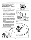
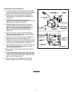
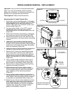
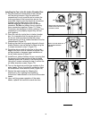
23. Reinstall the air intake chamber gasket (removed
in step 14) on the back lower portion of the new air
intake chamber box (Figure 51).
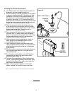
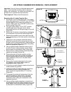
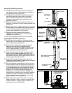
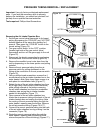
24. Install the new air intake chamber box to the
combustion chamber pipe. Using a small amount
of soapy water will help. Do not get any water
or soapy water on any electrical connections or
gas control components (see Figure 52). (NOTE:
UNDUE PRESSURE OR SUDDEN FORCE
SUCH AS HAMMERING OR BEATING ON
THE AIR CHAMBER BOX WITH ANY OBJECT
INCLUDING YOUR HANDS WILL DAMAGE THE
AIR INTAKE CHAMBER BOX AND RESULT IN
FAILURE TO THE HEATER’S OPERATION.
Figure 49.
AIR INTAKE
CHAMBER BOX
REMOVAL
CHAMBER GASKET
ROTATE FROM
LEFT TO RIGHT
AND
PULL OUTWARD
Figure 50.
RUBBER WIRE
PROTECTOR
WIRE HARNESS INSIDE
WIRE CHANNELING
AIR PRESSURE TUBING
CONNECTION
REAR SIDE OF
THE AIR INTAKE
CHAMBER BOX
Figure 51.
NEW AIR INTAKE
CHAMBER BOX
REINSTALL
CHAMBER GASKET
Figure 52.
AIR INTAKE
CHAMBER BOX
INSTALLATION
ROTATE FROM
LEFT TO RIGHT
AND
PUSH INWARD