


39
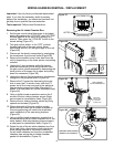
PRESSURE TUBING REMOVAL / REPLACEMENT
Important: Use only factory authorized replacement
parts. If you lack the necessary skills to properly
perform the installation, you should not proceed, but
get help from a qualified service technician.
Tools required: Phillips Head Screwdriver.
Removing the Air Intake Chamber Box:
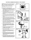
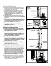
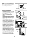
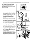
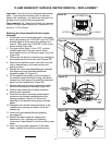
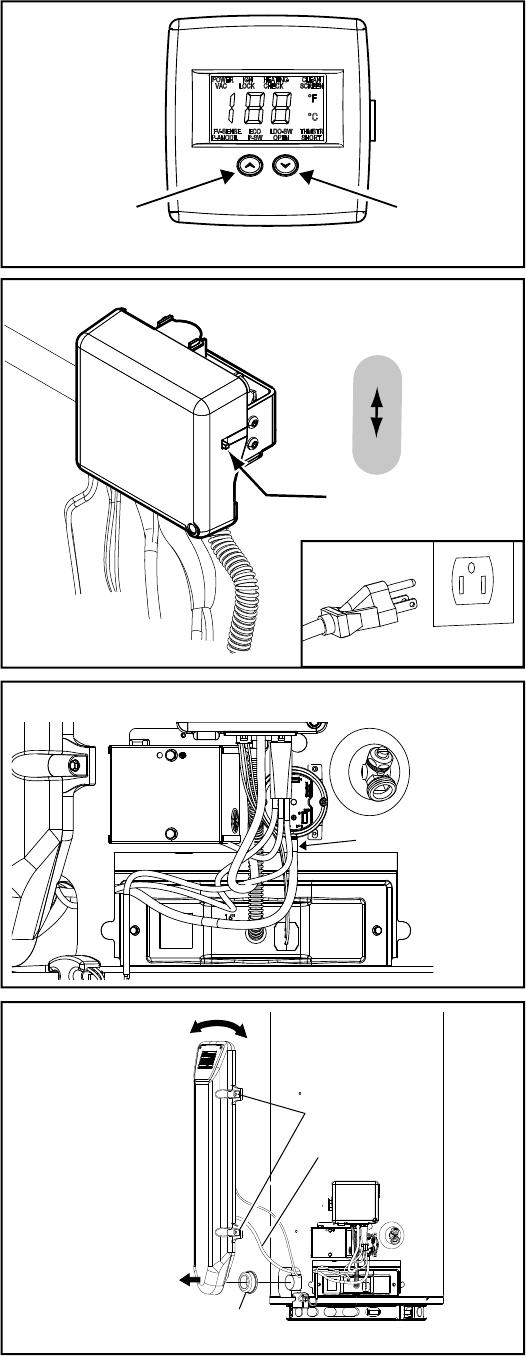
1. Set the gas control valve/thermostat to its lowest
setting by pressing the “COOLER” and “HOTTER”
buttons together at the same time holding for 1
second. Then press the “COOLER” button to the
lowest setting (Figure 74).
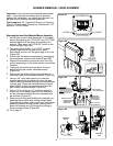
2. Turn gas control switch to the “OFF” position
(located right side of the gas control valve/
thermostat) and turn off the gas supply to the unit
(Figure 75).
3. Disconnect the electric connection by unplugging
the transformer from the wall outlet (Figure 75).
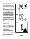
4. Remove the manifold cover/ outer door from the
unit by depressing on the lower portion and pulling
outward.
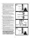
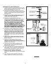
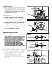
5. Remove the air pressure tubing from the air
pressure switch by pulling downward on the
tubing at the connection to the air pressure switch
(Figure 76).
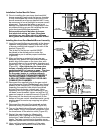
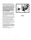
6. Using a phillips head screwdriver, remove the 4
screws securing the air intake chamber box to the
water heater’s side (Note: keep these screws in a
safe place for reinstallation later) (Figure 77).
7. Rotate the top of the air intake chamber box from
left to right (only a few inches in both directions)
while pulling outward at the bottom removing
the air intake chamber box from the combustion
chamber pipe saving the air intake chamber
gasket for reinstallation (Figure 77).
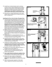
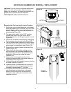
8. Upon removal of the air intake chamber box,
locate the air pressure tubing at the back of the air
intake chamber box and unplug the tubing. Note
the routing of the air pressure tubing through the
water heater’s opening near the bottom. Remove
the old air pressure tubing (Figures 76 & 77).
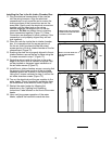
9. Connect the new air pressure tubing into the back
of the air intake chamber box by pushing it on the
connector (Figure 78).
10. Route the new air pressure tubing through the
water heater’s opening near the bottom (Note:
mirrors the position of the old tubing) (Figures 77).
Figure 76.
PRESSURE SWITCH
TUBING CONNECTION
Figure 77.
CHAMBER GASKET
ROTATE FROM
LEFT TO RIGHT
AND
PULL OUTWARD
SCREWS
AIR PRESSURE
TUBING
g
COOLER
HOTTER
Electronic Control Display
Figure 74.
ON/OFF
SWITCH
ON
OFF
Figure 75.
UNPLUGGED