


52
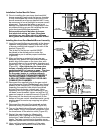
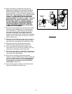
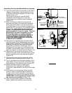
23. Turn on the gas supply to the unit and test the gas
supply line and union connections by brushing on
an approved noncorrosive leak detection solution
(Figure 116).
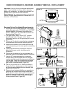
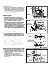
24. Turn on the electrical and the gas supplies to the
water heater. Plug in the electric connection from
the transformer to the electric outlet (Figure 113).
25. Restart the water heater by following the
directions on the “Lighting and Operating
Instructions” label located on the front of the water
heater .
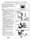
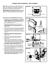
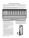
26. As the burner is heating (view flames through
viewport), test the manifold tube connection at
the gas control valve/thermostat by brushing on
an approved noncorrosive leak detection solution
(IMPORTANT: Do Not splash any solution onto
any electrical connections) (Figure 120).
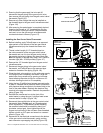
27. Upon verifying proper operation of the water
heater, replace the manifold cover/outer door.
IMPORTANT:
WHEN BRUSHING ON AN
APPROVED NONCORROSIVE
LEAK DETECTION SOLUTION,
DO NOT SPLASH SOLUTION
ONTO ELECTRICAL CON-
NECTIONS.
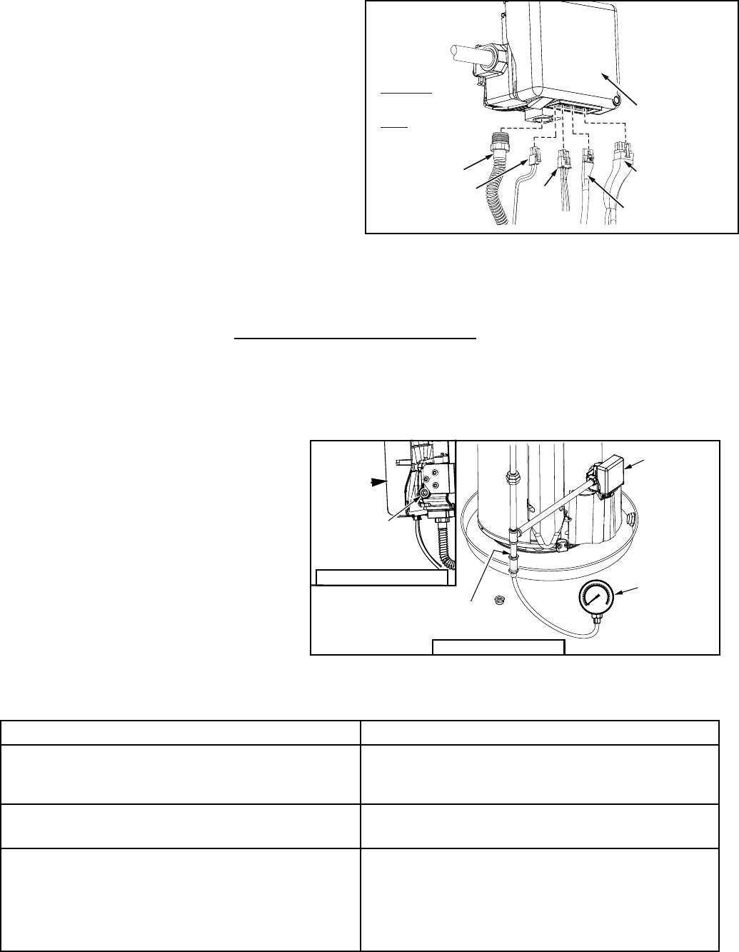
IGNITER/
FLAME
SENSE
CONNECTOR
MANIFOLD TUBE
POWER SUPPLY
TRANSFORMER
CONNECTOR
PRESSURE
SWITCH/FAN,
FV SENSOR
CONNECTOR
DISPLAY, ANODE
ROD CONNECTOR
GAS CONTROL
VALVE/THERMOSTAT
Figure 120.
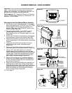
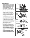
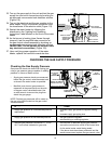
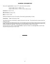
Checking the Gas Supply Pressure
Gas pressure checks are done with flowing gas
using a gas pressure gauge capable of reading
pressure in inches of water column.
GAS
PRESSURE
GAUGE
CONNECTED AT
PRESSURE TAP
GAS CONTROL
VALVE/
THERMOSTAT
SUPPLY GAS PRESSURE TEST
USE AN ALLEN
WRENCH TO REMOVE
AND REPLACE PLUG.
GAS CONTROL
VALVE/
THERMOSTAT
MANIFOLD GAS PRESSURE TEST
IF . . . . . . THEN
supply gas pressure is under desired pressure
requirement
• increase supply gas pressure regulator setting
and,
• increase supply gas piping size.
supply gas pressure is over desired pressure • add gas pressure regulator.
• reduce setting on existing regulator.
manifold gas pressure is more than +/- .3 inch
W.C. from values indicated on gas valve
• ensure there is adequate supply gas pressure
• ensure the main burner orifi ce is the correct size
for the water heater model being tested.
• if the above tests have been performed and the
results were correct replace the gas control valve.
Figure 121
•
•
Supply gas pressure checks are measured
before the gas control valve/thermostat and
as close to the water heater as possible.
Manifold (main burner) gas pressure is
measured at the pressure tap on the side
of the gas control valve/thermostat. Use
an allen wrench to remove the plug then
attach the gas gauge.
NOTE: Desired gas pressures will be noted on
the gas valve label located on the gas control
valve/thermostat.
CHECKING THE GAS SUPPLY PRESSURE