


14
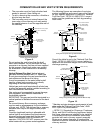
WATER HEATER OPERATION
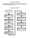
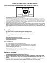
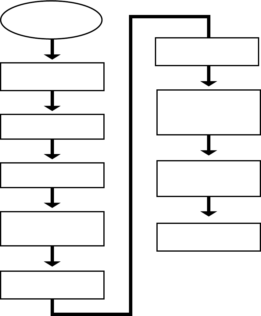
The figure below shows the water heater’s sequence of operation when a call for heat is initiated. The gas
control valve/thermostat will attempt to light the burner three times. If the flame sense rod in the burner/
manifold assembly does not detect ignition, the control will enter lockout mode indicated by the electronic
control display’s flashing of the appropriate status code.
SEQUENCE OF OPERATION
Main burner flame is detected by
flame sense rod. Air intake fan
and main burner will continue to
operate until water temperature
inside the tank reaches
temperature set point.
Gas valve/thermostat will do a
relay check (relay clicks will be
heard).
Display will show temperature
set point during call for heat.
System will verify pressure
switch operation and start a
5 second pre-purge, then air
intake fan will turn off.
Ignitor will start a 12 second
warm up period. “IGN” will
show on display.
Gas valve/thermostat will open
for 4 second trial for ignition
and fan will turn on.
Gas valve/thermostat is de-
energized and air intake fan
continues for a post purge time
of approximately 5 seconds.
Water heater returns to standby
mode.
Call for heat indicated by
flashing of display screen
status codes.
Draft Blower is energized.