53
* To check where threaded portion enters tank,
insert cotton swab between jacket opening and
fi tting. If cotton is wet, follow draining instructions
in the “Draining the Water Heater” section and then
remove fi tting. Put pipe dope or Tefl on
®
tape on the
threads and replace. When you are fi nished, follow
the steps in “Filling the Water Heater” section.
GAS WATER HEATER SIZING GUIDE
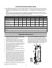
Use the following information as a guide to approximate the correct size water heater for the residence:
• 40 gallon size (28 gallon draw) for two bath residence -or one bath with an automatic clothes washer.
• 50 gallon size (35 gallon draw) for three bath residence - or two baths with an automatic clothes
washer.
• When a whirlpool tub is part of the home equipment, it is suggested that the water heater storage
tank capacity be selected based on the needs of the whirlpool tub. This method of tank sizing, will in
most cases, cancel all statements above concerning tank sizing.
• High fl ow or multiple shower head installations must be sized for at least a 20 minute draw.
Table 2:
Tub Capacity to Overfl ow
Outlet at:
80 gal. 90 gal. 100 gal. 110 gal. 120 gal. 130 gal. 140 gal. 150 gal.
(120ºF Water) Min. Stored
Water Capacity**
80 gal. 90 gal. 100 gal. 110 gal. 120 gal. 130 gal. 140 gal. 150 gal.
(140ºF Water*) Min. Stored
Water Capacity**
65 gal. 71 gal. 80 gal. 89 gal. 98 gal. 108 gal. 117 gal. 125 gal.
(@ 160ºF Water*) Min.
Stored Water Capacity**
54 gal. 59 gal. 66 gal. 74 gal. 82 gal. 90 gal. 97 gal. 104 gal.
*A thermostatic mixing valve set for a maximum temperature of 120° F is recommended to be installed to prevent a scalding hazard.
**Based on tub water temperature of 105º
Note: Because the desired fi ll time is normally 10 minutes, recovery capacity is not used for this calculation. All water used is supplied
by storage.
NOTE: The draw effi ciency of a gas or electric water heater storage tank is considered to be 70%.
A
C
B
D
E
F
G
H
I
6” (152.4 mm)
MAXIMUM AIR GAP
A. Water at the draft hood is water vapor which has
condensed out of the combustion products. This is
caused by a problem in the vent.
B. *Condensation may be seen on pipes in humid
weather or pipe connections may be leaking.
C. *The powered anode rod fi tting may be leaking.
D. Small amounts of water from temperature-pressure
relief valve may be due to thermal expansion or
high water pressure in your area.
E. *The temperature-pressure relief valve may be
leaking at the tank fi tting.
F. Water from a drain valve may be due to the valve
being slightly opened.
G. *The drain valve may be leaking at the tank fi tting.
H. Combustion products contain water vapor which
can condense on the cooler surfaces of the tank.
Droplets form and drip onto the burner or run on
the fl oor. This is common at the time of start-up
after installation and when incoming water is cold.
I. Water in the water heater bottom or on the fl oor
may be from condensation, loose connections, or
the relief valve. DO NOT replace the water heater
until a full inspection of all possible water sources
is made and necessary corrective steps taken.
Leakage from other appliances, water lines, or ground
seepage should also be checked.
LEAKAGE CHECKPOINTS
Figure 122


