


25
ELECTRONIC CONTROL DISPLAY REMOVAL / REPLACEMENT
Important: Use only factory authorized replacement
parts. If you lack the necessary skills to properly
perform the installation, you should not proceed, but
get help from a qualified service technician.
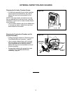
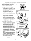
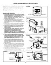
Removing the Electronic Control Display:
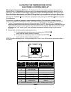
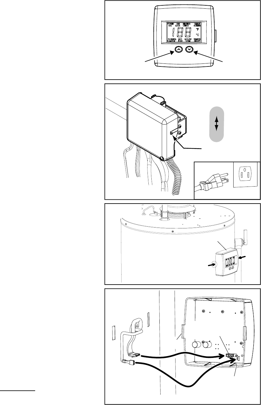
1. Set the gas control valve/thermostat to its lowest
setting by pressing the “COOLER” and “HOTTER”
buttons together at the same time holding for 1
second. Then press the “COOLER” button to the
lowest setting (Figure 26).
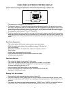
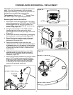
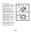
2. Turn gas control switch to the “OFF” position
(located right side of the gas control valve/
thermostat) and turn off the gas supply to the unit
(Figure 27).
3. Disconnect the electric connection by unplugging
the transformer from the wall outlet (Figure 27).
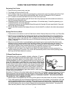
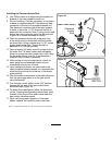
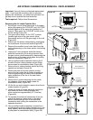
4. Remove the electronic control display by
squeezing in both sides of the display and
removing from the slots in the water heater’s front
(Figure 28).
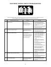
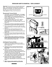
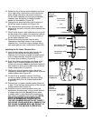
5. Unplug the electronic control display electrical
connector from the back of the electronic control
display by depressing the locking snap and pulling
out of the electronic control display electrical
connection, also remove the power anode wire
connector by pulling it off of the power anode
control display terminal (Figure 29).
Installing the Electronic Control Display:
6. Plug the power anode electrical wire terminal onto
the power anode connector terminal (Figure 29).
7. Insert the electronic control display electrical
connector into the electronic control display
electrical connection by aligning the connector
pins (note orientation of the connector pins) and
pressing down ensuring the electrical connector
snap is locked into place (Figure 29).
8. Install the electronic control display onto the front
of the water heater by squeezing both sides of
the electronic control display inserting the prongs
into the water heater’s slots (please note the
orientation of the electronic control display and
the routing the wiring inside so as not be pinched
between the display and the water heater’s front)
(Figure 28).
9. Turn on the electrical and the gas supplies to the
water heater. Plug in the electric connection from
the transformer to the electric outlet (Figure 27).
10. Restart the water heater by following the directions
on the “Lighting and Operating Instructions” label
located on the front of the water heater.
g
COOLER
HOTTER
Electronic Control Display
Figure 26.
ON/OFF
SWITCH
ON
OFF
Figure 27.
UNPLUGGED
Figure 29.
SLOT
POWER ANODE
CONTROL DISPLAY
TERMINAL
SLOT
ELECTRONIC CONTROL
DISPLAY ELECTRICAL
CONNECTION
PRONG
TO REMOVE OR TO INSTALL,
SQUEEZE BOTH SIDES OF THE
CONTROL DISPLAY.
Figure 28.
ELECTRONIC CONTROL DISPLAY