


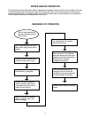
6
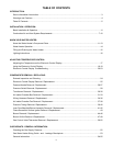
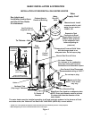
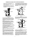
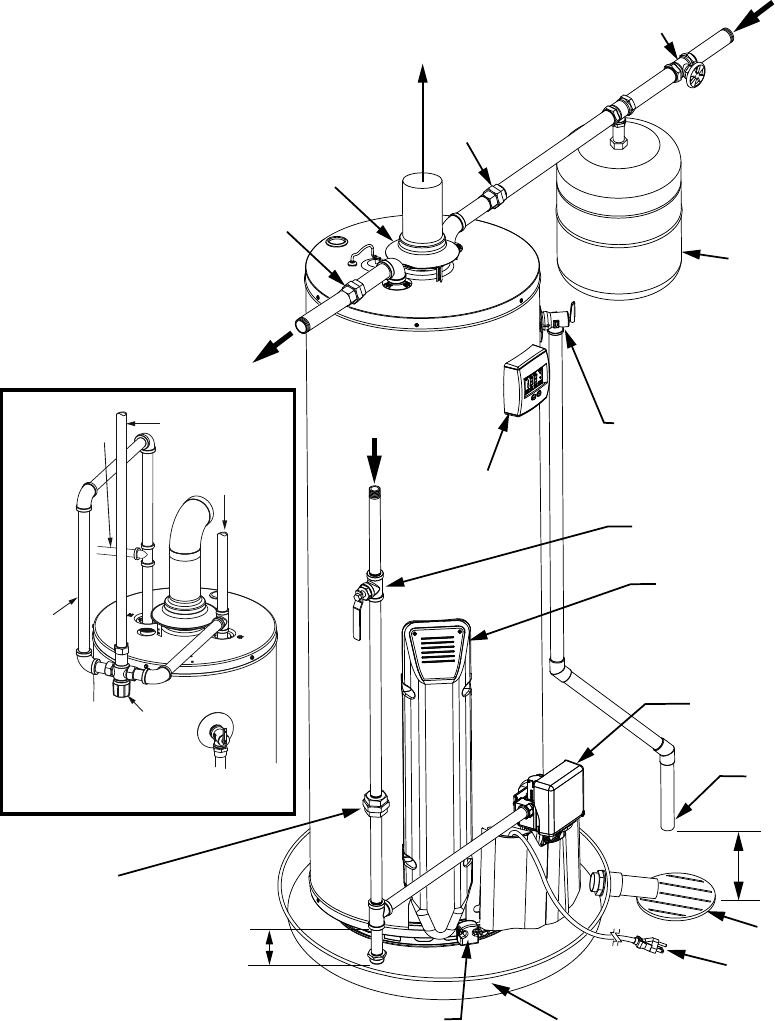
Exhaust Vent to
Ouside of Building
Union
Union
Water
Shut-Off
Valve
Water
Supply- Cold*
Expansion Tank
Pressurize to Equal
Supply Water Pressure*
(Relieve water pressure
on the expansion tank
before adjusting air
pressure.)
Temperature-Pressure Relief Valve
with discharge piped to an
adequate drain. Do not cap or plug.
6” Maximum Air Gap
NOTE: Local codes
may vary.
Drain
Gas Control Valve/Thermostat
Recommended setting of 120°F.**
Metal Drain Pan piped to an adequate drain.
NOTE: Drain pan diameter must be at least
2 inches wider than the diameter of the
water heater.
Sediment Trap
(Drip Leg) 3” Minimum.
Gas
Supply
To Fixtures - Hot
Air is drawn in for combustion.
Keep area clean and free from
flammables and flammable vapors.
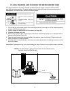
The water heater must be installed according to all local and state codes or in the absence of local
and state codes, the “National Fuel Gas Code”’ ANSI Z223.1(NFPA 54)- current edition.
INSTALLATION OF RESIDENTIAL GAS WATER HEATER
See Labels and
Installation Instructions
and Use & Care Guide
for clearances.
* NOTE: If on a well system the expansion tank should be set to the maximum pressure of the pump tank.
** White-Rodgers® gas control valve/thermostat shown in this figure.
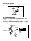
*Massachusett: Install
a vacuum relief in cold
water line per section
19 MGL 142.
Do not cap or plug.
Union
Manual Gas Shut-off Valve
Untempered
Hot Water
Tempered Water
To Fixtures
Cold
Water
Inlet
Hot
Water
Outlet
Mixing Valve
(Set to 120°F)
Follow the Mixing Valve
Manufacturer’s Instructions
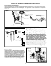
Control
Display
FV Sensor
Bracket
Air Intake Chamber
Electrical Plug
Use Draft Hood
supplied with unit
BASIC INSTALLATION & OPERATION
Figure 1