


51
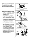
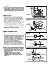
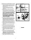
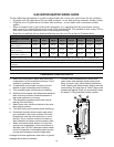
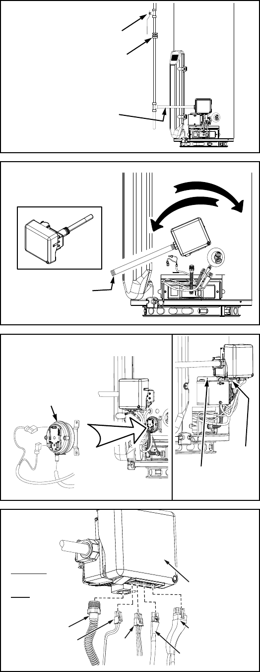
11. Ensuring that the gas supply line is turned off,
disconnect the gas piping at the ground joint union,
then remove the gas piping from the gas control valve/
thermostat (Figure 116).
12. Remove any other fittings that may be installed on
the threaded pipe to the gas control valve/thermostat
(Figure 116).
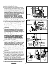
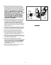
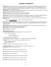
13. After ensuring the water heater is completely drained,
thread a short length of 1/2” threaded pipe into the
inlet connection of the gas control valve/thermostat
and use it to turn the gas control valve/thermostat
counterclockwise to remove (Figure 117).
Installing the Gas Control Valve/Thermostat:
14. Before installing, apply Teflon® tape or an approved
pipe sealant on the threads of the new gas control
valve/thermostat (only the threads that screw into
tank).
15. Thread a short length of 1/2” threaded pipe into
the inlet connection of the new gas control valve/
thermostat and use it to turn the gas control valve/
thermostat clockwise to tighten into place (Note: Do
Not over tighten or damage may result, but it needs to
be water tight (Min. 35 foot pounds) (Figure 117).
16. Remove the 1/2” threaded pipe from the gas control
valve/thermostat.
17. Reconnect the gas piping to the gas control valve/
thermostat, use Teflon® tape or an approved pipe
sealant on threads of the piping (Figure 116).
18. Close the drain valve and turn on the cold water supply
line filling the tank completely with water. Purge the
water lines of any excess air by opening a hot water
faucet allowing the water to flow for a minimum of 3
minutes, allowing the tank to fill completely.
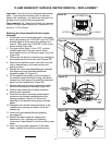
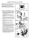
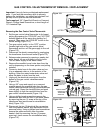
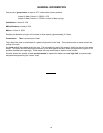
19. Using the two (2) phillips head screws removed earlier
in step 10, reattach the air pressure switch (orientation
with pressure tubing connector to the down side) to the
front of the water heater. Reattach the electrical flag
terminal to the pressure switch. Reattach the pressure
tubing (Figure 118).
20. Reinstall the transformer box to the front of the
water heater by using the one (1) phillips head screw
removed earlier in step 9 (Figure 118).
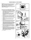
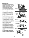
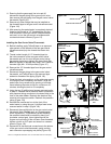
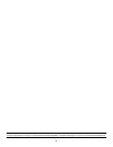
21. Reconnect the manifold tube to the gas control valve/
thermostat (Note: Do Not apply any thread sealant
at this connection). To prevent any cross threading
the manifold tube should be started by hand (turn
clockwise -natural gas). Upon tightening with the
fingers and confirming it has not been cross threaded,
tighten nut with an 3/4” open end wrench or crescent
wrench (Figure 119).
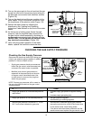
22. Reconnect all the electrical connections to the bottom
of the gas control valve/thermostat, gently pushing
each connector up snapping into place (Figure 119).
Teflon
®
is a registered trademark of E.I. Du Pont De Numours and Company.
Figure 116.
GROUND JOINT UNION
GAS SHUT-OFF
GAS PIPING
ROTATE TO:
Figure 117.
INSTALL
REMOVE
SHORT LENGTH OF
1/2” TREADED PIPE
GAS CONTROL VALVE /
THERMOSTAT
ROTATE TO:
Figure 118.
PRESSURE
SWITCH
MANIFOLD
TUBE
SCREW AT
TRANSFORMER
BOX
IMPORTANT:
WHEN BRUSHING ON AN
APPROVED NONCORROSIVE
LEAK DETECTION SOLUTION,
DO NOT SPLASH SOLUTION
ONTO ELECTRICAL CON-
NECTIONS.
IGNITER/
FLAME
SENSE
CONNECTOR
MANIFOLD TUBE
POWER SUPPLY
TRANSFORMER
CONNECTOR
PRESSURE
SWITCH/FAN,
FV SENSOR
CONNECTOR
DISPLAY, ANODE
ROD CONNECTOR
GAS CONTROL
VALVE/THERMOSTAT
Figure 119.