


46
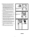
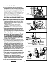
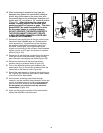
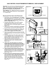
16. After confirming no material of any type are
between door gasket and combustion chamber
shield, align the screws on the inner door with
the screw holes on the combustion chamber and
tighten with 1/4” nut driver or 1/4” socket & ratchet
(Figure 97). After tightening the inner door
screws, visually inspect area around door
gasket and skirt for spaces or gaps. The door
gasket MUST be sealed completely in order
for the water heater to perform properly.
DO NOT OPERATE THE WATER HEATER IF
THE DOOR GASKET DOES NOT CREATE
A SEAL BETWEEN MANIFOLD DOOR AND
COMBUSTION CHAMBER.
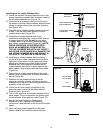
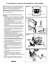
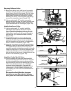
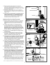
17. Reconnect the manifold tube to the gas control valve/
thermostat (Note: Do Not apply any thread sealant
at this connection). To prevent any cross threading
the manifold tube should be started by hand (turn
clockwise -natural gas). Upon tightening with the
fingers and confirming it has not been cross threaded,
tighten nut with an 3/4” open end wrench or crescent
wrench (Figure 100).
18. Reconnect all the electrical connections to the bottom
of the gas control valve/thermostat, gently pushing
each connector up snapping into place (Figure 100).
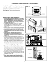
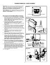
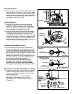
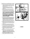
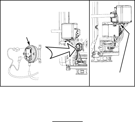
19. Reconnect the electrical flag terminals and air
pressure tubing to pressure switch (Figure 101).
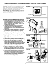
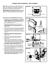
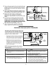
20. Turn on the electrical and the gas supplies to the
water heater. Plug in the electric connection from the
transformer to the electric outlet (Figure 94).
21. Restart the water heater by following the directions on
the “Lighting and Operating Instructions” label located
on the front of the water heater.
22. As the burner is heating (view flames through
viewport), test the manifold tube connection at the gas
control valve/thermostat by brushing on an approved
noncorrosive leak detection solution (IMPORTANT:
Do Not splash any solution onto any electrical
connections) (Figure 100).
23. Upon verifying proper operation of the water heater,
replace the manifold cover/outer door.
Figure 101.
PRESSURE
SWITCH
MANIFOLD
TUBE