


7
COMBUSTION AIR AND VENT SYSTEM REQUIREMENTS
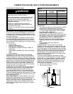
Table 1:
BTUH Input
Minimum Square
Feet with
8’ Ceiling
Typical Room
with 8’ Ceiling
30,000 188 9 x 21
45,000 281 14 x 20
60,000 375 15 x 25
75,000 469 15 x 31
90,000 563 20 x 28
105,000 657 20 x 33
120,000 750 25 x 30
135,000 844 28 x 30
IMPORTANT:
• The area must be open and be able to provide
the proper air requirements to the water
heater. Areas that are being used for storage
or contain large objects may not be suitable
for water heater installation.
• Water heaters installed in open spaces in
buildings with unusually tight construction may
still require outdoor air to function properly. In
this situation, outside air openings should be
sized the same as for a confined space.
• Modern home construction usually requires
supplying outside air into the water heater
area.
• Room exhaust fans may effect air
requirements.
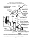
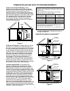
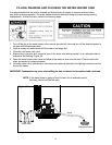
Confi ned Space: For the correct and proper
operation of this water heater, ample air must be
supplied for the combustion, ventilation, and dilu-
tion of fl ue gases. Small enclosures and confi ned
areas must have two permanent openings so that
suffi cient fresh air can be drawn from outside of
the enclosure. One opening shall be within 12
inches of the top and one within 12 inches of the
bottom of the enclosure.
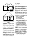
The size of each opening (free area) is deter-
mined by the total BTUH input of all gas utilization
equipment (i.e., water heaters, furnaces, clothes
dryers, etc.) and the method by which the air is
provided. The BTUH input can be found on the
water heater rating plate. Additional air can be
provided by two methods:
1. All air from inside the building.
2. All air from outdoors.
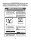
CLOSET
OR
OTHER
CONFINED
SPACE
12” MAXIMUM
PERMANENT
OPENINGS TO
THE OUTSIDE OR
ADDITIONAL
ROOMS WITHIN
THE BUILDING
12” MAXIMUM
Combustion Air Requirements:
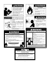
WARNING
Carbon Monoxide Warning
Water heater must be vented to outdoors.
Vent must be installed by a qualified technician using
the local and state codes or, in the absence of local
and state codes, the National Fuel Gas Code,
ANSI Z223.1 (NFPA 54) - current edition, and/or the
installation instructions.
Examples of a qualified technican include: gas
technicians, authorized gas company personel, and
authorized service persons.
Failure to so do can result in death or carbon monoxide
poisoning.
IMPORTANT: Air for combustion and ventilation
must not come from a fl ammable or corrosive at-
mosphere. Any failure due to fl ammable or corro-
sive elements in the atmosphere is excluded from
warranty coverage.
The following types of installation (not limited to
the following) will require outdoor air for combus-
tion due to chemical exposure and may reduce
but not eliminate the presence of corrosive chemi-
cals in the air:
• beauty shops
• photo processing labs
• buildings with indoor pools
• water heaters installed in laundry, hobby, or
craft rooms
• water heaters installed near chemical storage
areas
• water softeners
Combustion air must be free of acid-forming
chemicals such as sulfur, fl uorine, and chlorine.
These elements are found in aerosol sprays, de-
tergents, bleaches, cleaning solvents, air freshen-
ers, paint, and varnish removers, refrigerants, and
many other commercial and household products.
When burned, vapors from these products form
highly corrosive acid compounds. These prod-
ucts should not be stored or used near the water
heater, air inlet, or air intake path.
Combustion and ventilation air requirements are
determined by the location of the water heater.
The water heater may be located in either an
open (unconfi ned) area or in a confi ned area or
small enclosure such as a closet or small room.
Confi ned spaces are areas with less than 50 cubic
feet for each 1,000 BTUH of the total input for all
gas-using appliances.
Unconfi ned Space: A water heater in an uncon-
fi ned space uses indoor air for combustion and
requires at least 50 cubic feet for each 1,000
BTUH of the total input for all gas appliances. The
table below shows a few examples of the mini-
mum square footage (area) required for various
BTUH inputs.
Figure 2.