


90 Status Reporting
The RQS Bit
Whenever the Agilent SAS requests service, it sets the SRQ interrupt line true and latches RQS into bit 6 of the Status Byte
register. When the controller services the interrupt, RQS is cleared inside the register and returned in bit position 6 of the
response. The remaining bits of the Status Byte register are not disturbed.
The MSS Bit
This is a real-time (unlatched) summary of all Status Byte register bits that are enabled by the Service Request Enable
register. MSS is set whenever the Agilent SAS has at least one reason (and possibly more) for requesting service. Sending
*STB? reads the MSS in bit position 6 of the response. No bits of the Status Byte register are cleared by reading it.
Determining the Cause of a Service Interrupt
You can determine the reason for an SRQ by the following actions:
■ Use a serial poll or the *STB? query to determine which summary bits are active.
■ Read the corresponding Event register for each summary bit to determine which events caused the summary bit to be
set. When an Event register is read, it is cleared. This also clears the corresponding summary bit.
■ The interrupt will recur until the specific condition that caused each event is removed. If this is not possible, the event
may be disabled by programming the corresponding bit of the status group Enable register or NTR|PTR filter. A faster
way to prevent the interrupt is to disable the service request by programming the appropriate bit of the Service Request
Enable register.
Service Request Enable Register
This register is a mask that determines which bits from the Status Byte register will be ORed to generate a service request
(SRQ). The register is programmed with the *SRE common command. When the register is cleared, no service requests
can be generated to the controller.
Output Queue
The Output Queue is a first-in, first-out (FIFO) data register that stores Agilent SAS-to-controller messages until the
controller reads them. Whenever the queue holds one or more bytes, it sets the MAV bit (4) of the Status Byte register. If
too many unread error messages are accumulated in the queue, a system error message is generated (see appendix D). The
Output Queue is cleared at power on and by *CLS.
Initial Conditions At Power On
Status Registers
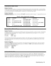
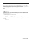
When the Agilent SAS is turned on, a sequence of commands initializes the status registers. For the factory-default *RST
power-on state, Table 8-4 shows the register states and corresponding power-on commands.
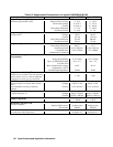
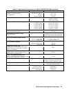
Table 8-4. Default Power On Register States
Register Condition Caused By
Operation PTR; Questionable PTR All bits = 1
STAT:PRE
Operation NTR; Questionable NTR All bits = 0
STAT:PRE
Operation Event; Questionable Event All bits = 0
*CLS
Operation Enable; Questionable Enable All bits = 0
STAT:PRE
Standard Event Status Enable All bits = 0
1
*ESE 0
Status Byte All bits = 0
*CLS
Status Request Enable All bits = 0
1
*SRE 0
Output Queue Cleared
*CLS
1
If PSC=1. If PSC = 0, the last previous state before turn on is recalled. The value of PSC is stored in nonvolatile memory.