


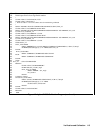

Digital Port Functions 119
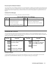
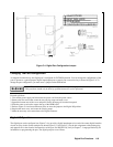
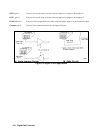
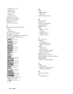
Figure C-4. Digital Port Configuration Jumper
Changing The Port Configuration
As shipped from the factory, the digital port is configured for FLT/INH operation. You can change the configuration of the
port to operate as a general-purpose digital input/output port to control your custom circuitry as shown in Figure C-4. To
change the port configuration, you must move a jumper on the GPIB board.
Shock Hazard. Hazardous voltage can remain inside the power supply even after it has been turned off.
This procedure should only be done by qualified electronics service personnel.
Proceed as follows:
1. Turn off the power supply and disconnect the power cord from the power source.
2. Remove the four screws that secure the two carrying straps and outer cover.
3. Spread the bottom rear of the cover and pull it back to disengage it from the front panel.
4. Slide the outer cover back to expose the top of the GPIB board.
5. Refer to Figure C-4 and use needle-nose pliers to move the jumper to the Digital I/O position.
6. Replace the outer cover, and secure the carrying straps.
7. Make the necessary wire connections to the digital connector.
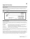
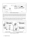
Digital I/O Operation
The digital port can be configured (see Figure C-4) to provide a digital input/output to be used with custom digital interface
circuits or relay circuits. Some examples are shown Figure C-5. See Figure C-1 for the pin assignments of the mating plug
and appendix A for the electrical characteristics of the port. See DIG:DATA[:VAL] in chapter 7 - Language Dictionary for
information on programming the port. The digital port pins are as follows:
1 INNER COVER
2 INPUT RAIL LEDS
3 GPIB BOARD
4 CONFIGURATION JUMPERS