


18 General Information
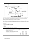
■ There is no restriction on the spacing between points in either voltage or current, but the points must be monotonic.
Voltage values must be sent in increasing order of magnitude; current values must be sent in equal or decreasing order
of magnitude. For an Agilent E4350B for example: (1,8) (50,7.8) (55,7.5) (56,7) (57, 6) (58, 4) (59,1).
■ Each table point, when combined with the table offset, cannot exceed the unit’s maximum voltage, current, or power.
■ A table cannot be deleted or redefined while it is selected with CURRent:TABLe:NAME.
■ Maximum Power
≤
480 W
■ ∆
V/
∆
I
≥
.25
Ω
for Agilent E4350B;
≥
1
Ω
for Agilent E4351B
Voc
≤
65V (Agilent E4350B); 130V (Agilent E4351B)
Isc
≤
8A (Agilent E4350B); 4A (Agilent E4351B)
The Vmp and Imp points are calculated internally and need not be supplied.
NOTE: When the unit detects an invalid voltage/current point, it will generate an error, light the ERR annunciator on
the front panel, and will not use the new parameters. Instead, it will operate with the last valid table settings.
Therefore, although it may seem that the unit is operating correctly, it will NOT be using the values that you
have programmed for table mode.
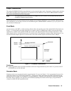
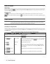
Table Offsets:
A new table can be generated by applying a limited voltage or current offset to an existing table. This can be helpful in
simulating temperature, angular, rotational, or aging changes. Offset values are non-cumulative, they can be either positive
or negative, and can be applied to any table. Each time a voltage or current offset is programmed, a new I-V curve is
calculated based on the user-defined table that is presently active and the supplied offset values. Offset values affect the
original I-V curve as follows:
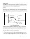
Positive Voltage Offsets:
The original curve is shifted to the right (È) along the positive voltage axis, and the first
point on the curve is extended horizontally at Isc until it intersects the current axis. Thus,
the new Voc equals the original Voc plus the offset value. An error will be generated if the
offset causes the maximum allowed Voc or the power limit to be exceeded.
Negative Voltage Offsets:
The original curve is offset to the left (Ç) along the positive voltage axis, and terminated at
the current axis. The curve points that are not used because they extended beyond the
current axis are not deleted; they will be valid once again if the negative voltage offset is
reduced or eliminated.
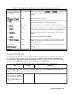
Positive Current Offsets:
The original curve is offset up (É) along the positive current axis, and the last point on the
curve will be extended (at the same slope that was present in the original table curve at
Voc) until it intersects the voltage axis at a new, slightly higher Voc value. The new Isc
equals the original Isc plus the offset value. An error will be generated if the offset causes
the maximum allowed Isc, Voc, or the power limit to be exceeded.
Negative Current Offsets:
The original curve is offset down (Ê) along the positive current axis, and terminated at the
voltage axis at a new, lower Voc value. The curve points that are not used because they are
extended beyond the voltage axis are not deleted; they will be valid once again if the
negative current offset is reduced or eliminated.
Front panel operation:
You can use the front panel when the unit is operating in Table mode. To do this, press the Local key whenever the front
panel RMT annunciator is on. Be aware however, that any voltage and current values that you enter from the front panel
will have no effect on the unit while it is in Table mode. The front panel values will take effect as soon as the unit is placed
in Fixed mode. Likewise, the OCP function only takes effect in Fixed mode. All other functions such as Local, Error,
Output On/Off, Protect are active while the unit is operating in Simulator mode.