


54 Remote Programming
Examples
Most examples given here are generic, without regard to the programming language or type of GPIB interface. Because
SCPI commands are sent as ASCII output strings within the programming language statements, the SCPI syntax is
independent of both programming language and interface. The examples are followed by sample program code written for
an Agilent BASIC controlled GPIB interface.
Programming Voltage and Current
Note The Agilent SAS responds simultaneously to both digital and analog programming inputs. If it is receiving an
input over the GPIB and a corresponding input from the front panel (and from the analog programming port),
the output will be the algebraic sum of the inputs. (Analog programming applies in Fixed mode only.)
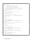
The following statements program both voltage and current and return the actual output from the sense terminals:
OUTP OFF Disable the output.
VOLT 55;CURR 2.5 Program the voltage and current.
VOLT?;CURR? Read back the programmed levels.
OUTP ON Enable the output.
MEAS:VOLT?;MEAS:CURR? Read back the outputs from the sense terminals.
Programming Protection Circuits
This example programs the voltage and current, programs an overvoltage protection value, and turns on the overcurrent
protection. It then reads back all the programmed values. Note the required use of the optional LEVel header in this
example (see "Moving Among Subsystems" for more information).
VOLT:LEV 55;PROT 60 Program the voltage and overvoltage protection.
CURR:LEV 3;PROT:STAT ON Program the current and overcurrent protection.
VOLT:LEV?;PROT?;:CURR:LEV?;PROT:STAT? Read back the programmed values.
Programming Units in Auto-Parallel
Refer to “Auto-Parallel Programming Cautions” in chapter 4 before using Agilent SAS units in
auto-parallel mode.
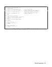
The following examples illustrate how to program a master unit and a slave unit that are connected in auto-parallel mode.
The master unit is at address 705; the slave unit is at address 706. Refer to chapter 4 for connection information. Refer to
chapter 7 for details about specific programming commands. The first example illustrates auto-parallel operation in
Simulator mode.
1000 ! 2 Units in auto-parallel - Simulator Mode
1010 OUTPUT 705;”*RST” Resets the master unit.
1020 OUTPUT 706;”*RST” Resets the slave unit.
1030 OUTPUT 705;”CURR:SAS:ISC 4;IMP 3;:VOLT:SAS:VOC 60;VMP 40” Program curve data for master unit
1040 OUTPUT 706;”CURR:SAS:ISC 0;IMP 0;:VOLT:SAS:VOC 60;VMP 40” Program curve data for slave unit
1050 OUTPUT 705;”CURR:MODE:SAS” Selects simulator mode for master unit.
1060 OUTPUT 706;”CURR:MODE:SAS” Selects simulator mode for slave unit
1070 OUTPUT 705;”OUTP:STAT ON” Enables the output for master unit.
1080 OUTPUT 706;”OUTP:STAT ON” Enables the output for slave unit.