


32 User Connections
of at the load, but with a 3% to 5% increase in voltage at the output terminals. Bundle or tie wrap the load leads to minimize
inductance and reduce noise pickup.
CV Regulation
The Fixed mode voltage load regulation specification in appendix A applies at the output terminals of the Agilent SAS.
When remote sensing, this specification must be adjusted by adding 3 mV to the voltage load regulation specification for
each 1-volt change in the positive load lead due to a change in load current.
Because the sense leads are also part of the unit’s feedback path, keep the resistance of the sense leads low in order to obtain
the best performance. The additional load regulation due to resistance in the sense leads is given by the formula:
Regulation in millivolts =
(total load lead drop) * (total sense lead resistance)
K
where K = 3 for E4350B; 7 for E4351B
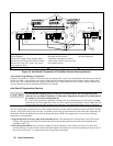
Overvoltage Protection Considerations
The OVP circuit senses the voltage at the output terminals, not at the sense terminals. With remote sensing, the voltage
sensed by the OVP circuit will be higher than the voltage being maintained at the load. Therefore, when using remote
sensing, you must program the OVP high enough to compensate for the expected voltage drop between the output and the
load.
Output Rating
The rated output voltage and current specification in appendix A applies at the output terminals of the Agilent SAS. With
remote sensing, any voltage dropped in the load leads causes the unit to increase the voltage at the output terminals so it can
maintain the proper voltage at the load (see Remote Voltage Sensing). If you attempt to operate at the full-rated output at
the load, this may force the voltage at the output terminals to exceed the unit’s rated output.
This will not damage the unit, but may trip the OVP (overvoltage protection) circuit, which senses the voltage at the output.
When operated beyond its rated output, the unit’s performance specifications are not guaranteed, although typical
performance may be good. If the excessive demand on the unit forces it to lose regulation, the Unr annunciator will indicate
that the output is unregulated.
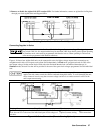
Output Noise
Any noise picked up on the sense leads also appears at the output of the Agilent SAS and may adversely affect the load
voltage regulation. Be sure to twist the sense leads to minimize external noise pickup and route them parallel and close to
the load leads. In noisy environments, it may be necessary to shield the sense leads. Ground the shield only at the Agilent
SAS. Do not use the shield as one of the sense conductors.
Stability
In Simulator and Table modes, the unit is stable with constant current, constant resistance, constant voltage, and any
capacitive loads. Inductive loads should be kept less than 200µH.
In Fixed mode, the unit is stable if the output capacitance is less than 2000µF.