


34 User Connections
+S
-S
+
-
2
1
+
-
+240 VDC MAX
-
-
I
-
IM
IP
IP
+
S
-
S
+--
I
SAS
P
A
B
3
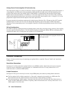
SENSE
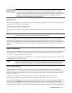
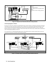
Local
Remote
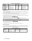
Load Connection
ô Load
í Analog Connector
Set switch for local or optional remote
sensing
Connect for remote sensing (optional)
Figure 4-5. Multiple Load Connection (Remote Sensing Optional)
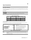
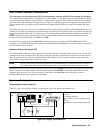
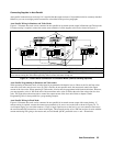
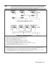
Connecting Supplies in Parallel
In most cases, units can be connected in straight parallel mode as shown in Figure 4-6 without any master/slave distinction,
and without any wiring to the analog connectors. This is possible because of the relatively high output impedance of each
unit. All units that are connected in straight parallel mode must be programmed with identical I-V curves or table data.
Remote sensing may be employed on all units if desired, but in many cases will have only a minimal effect on performance
due to the high output impedance of each unit.
If, for some reason, it is required that the output currents of all paralleled units be accurately matched, then you must use
auto-parallel connections as described in the following paragraphs.
+
-
-
+-
IM IM
SAS
P IM S S
+240 VDC MAX
-
-
I
1
+
-
+240 VDC MAX
-
-
I
+
-
+S
-
S
A
A
B
+--
I
-
+-+--
I
+-
-+-
+--
I
+240 VDC MAX
-
-
I
A
IM IM
SAS
P IM S S
IM IM
SAS
P IM S S
-
S
+S
-
S
+S
2
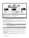
Analog Connectors (used for optional remote sensing) ô Load
Set all units to either local sensing or remote sensing Optional remote sense connections
Figure 4-6. Straight Parallel Connections (Remote Sensing Optional)