


30 User Connections
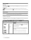
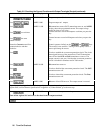
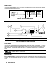
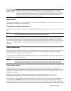
Digital Connector
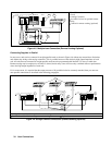
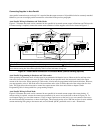
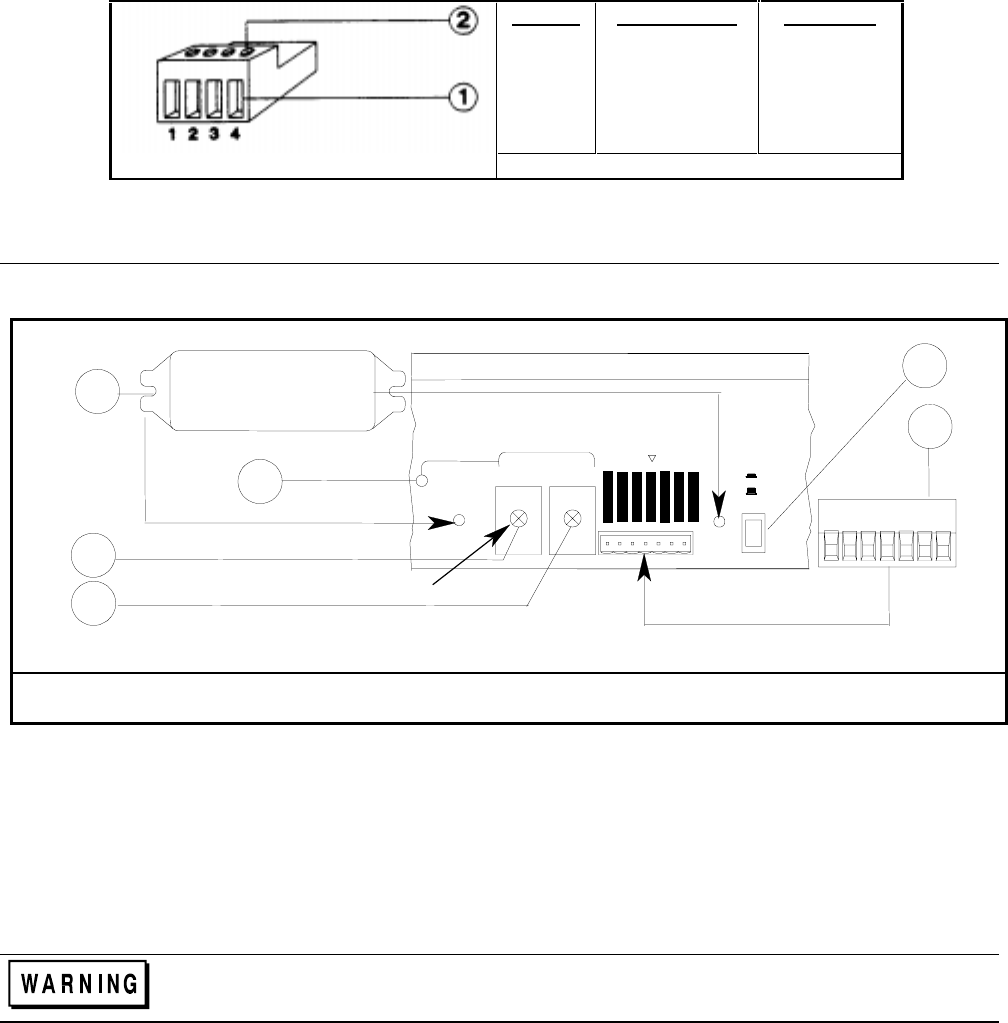
This connector, which is on the rear panel, is for connecting fault/inhibit, digital I/O, or relay link signals. The connector
accepts wires sizes from AWG 22 to AWG 12.
Pin No.
1
2
3
4
Fault/Inhibit
1
FLT OUTPUT
FLT OUTPUT
INH INPUT
INH COMMON
Digital I/O
OUT 0
OUT 1
IN/OUT 2
COMMON
Insert Wires ô Tighten Screws
1
Factory default function is FAULT/INHIBIT.
Figure 4-2. Rear Panel Digital Connector
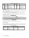
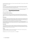
Load Connections
+
-
-
I
-
IM
IP
+
S
-
S
+240 VDC
-
SENSE
Local
Remote
-
I
SAS
P
1
2
5
6
3
4
M4 x 0.7 x 8mm
+
-
P
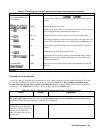
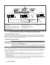
Output Safety Cover ô + Output Terminal í - Output Terminal
÷ Chassis ground (Earth) û Output Sense Switch ø Analog Connector
Figure 4-3. SAS Rear Panel Output Connections
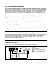
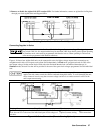
Output Isolation
The output of the Agilent SAS has dc isolation from earth ground. Either output terminal may be grounded, or an external
voltage source may be connected between either output and ground. However, both output terminals must be kept within
±
240 Vdc of ground. An earth ground terminal is provided on the rear panel for convenience, such as grounding wire
shields.
The earth ground terminal on the rear panel is a low-noise signal ground for convenience only. It is not
designed to function as a safety ground.
Capacitive Loads
In Fixed Mode Operation, the maximum external capacitance that may be added to the output without causing instability
is 2,000 µF. This is also the maximum capacitance value that can be safely discharged by the OVP (overvoltage protection)
circuit.