


User Connections 35
Connecting Supplies in Auto-Parallel
Auto-parallel connections are used only if it is required that the output currents of all paralleled units be accurately matched.
Otherwise you can use straight parallel connections as described in the previous paragraphs.
Auto-Parallel Wiring in Simulator and Table Modes
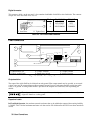
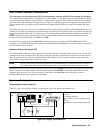
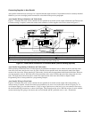
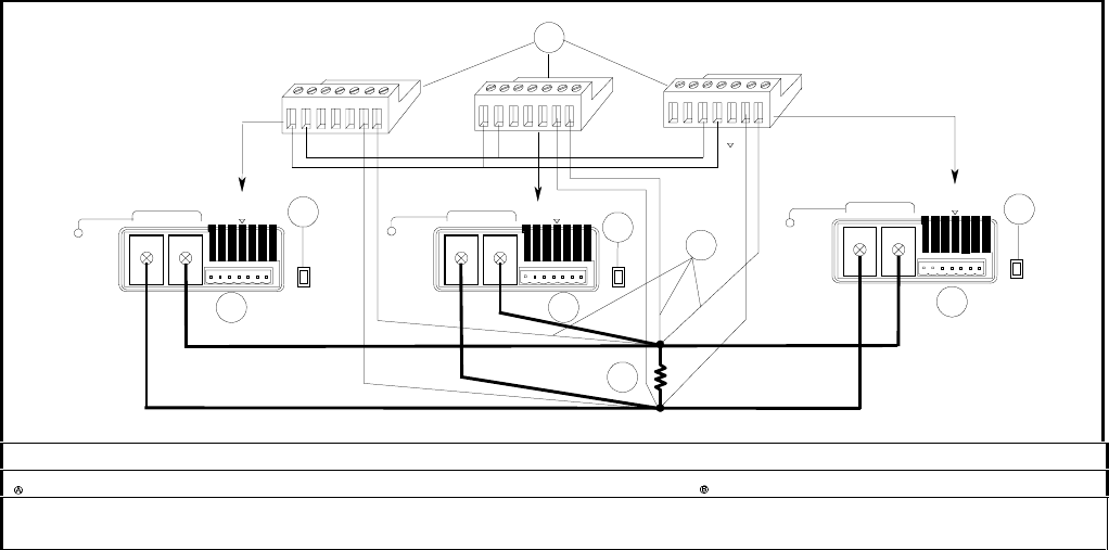
Figure 4-7 illustrates how units can be connected in auto-parallel for increased current output in Simulator and Table modes.
If remote sensing is required, connect the remote sense terminals of all the supplies to the load as shown in Figure 4-7.
+
-
-
+-
IM IM
SAS
P IM S S
+240 VDC MAX
-
-
I
1
+
-
+240 VDC MAX
-
-
I
+
-
+S
-
S
+IP
2
A
A
3
B
4
-
IP
+--
I
I
-
SAS
-
+-+--
I
+-
-+-
+--
I
+240 VDC MAX
-
-
I
+IP
2
A
-
IP
IM IM
SAS
P IM S S
IM IM
SAS
P IM S S
P
SLAVE
SLAVE
MASTER
-
S
+S
-
S
+S
Analog Connectors ôSlave Units í Master Unit ÷ Load
Set all units to either local sensing or remote sensing. Optional remote sense connections
Note that because there is already an output impedance associated with the units in Simulator and Table modes, in many
cases remote sensing has little effect especially if the load lead resistance is kept low.
Figure 4-7. Auto-Parallel Connection in Simulator Mode (Remote Sensing Optional)
Auto-Parallel Programming in Simulator and Table modes
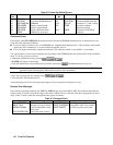
When operating in Simulator mode, all units must be programmed with identical curves. However the Isc and Imp values
sent to the slave units must be set to zero (0). This is because in auto-parallel mode, the master unit controls the output
current of the slave units. When operating in Table mode, all units must be programmed with identical table data. However,
you must append a value of -999 at the end of the current data and a value of +999 at the end of the voltage data for slave
units. This again allows the master unit to control the output current of the slave units. Refer to chapter 6 under
Programming Units in Auto-parallel for a programming example.
Auto-Parallel Wiring in Fixed Mode
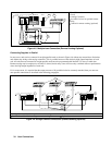
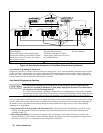
Figure 4-8 illustrates how units can be connected in auto-parallel for increased current output with current sharing. If
remote sensing is required, connect the remote sense terminals of the master unit to the load as shown in Figure 4-8. To
avoid output ringing, you can either connect a 2.2 µF or larger capacitor across the load, or you can connect a filter across
the current monitoring connections as shown in the figure. This network consists of two 200 ohm resistors in series with the
current monitoring lines going to the master unit, and a 68 ohm/0.1µF RC paralleled across + and − IP terminals.