


36 User Connections
+
-
-
+-
IM IM
SAS
P IM S S
+240 VDC MAX
-
-
I
1
+
-
+240 VDC MAX
-
-
I
+
-
+S
-
S
+IP
2
B
A
3
C
5
-
IP
+--
I
I
-
IM
-
+-+--
I
6
+-
-+-
+--
I
+240 VDC MAX
-
-
I
+IP
2
B
-
IP
IM IM
SAS
P IM S S
IM IM
SAS
P IM S S
P
Slave
Slave
Master
68
200
200
0.1uF
.
.
2.2uF
4
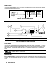
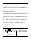
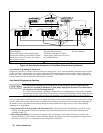
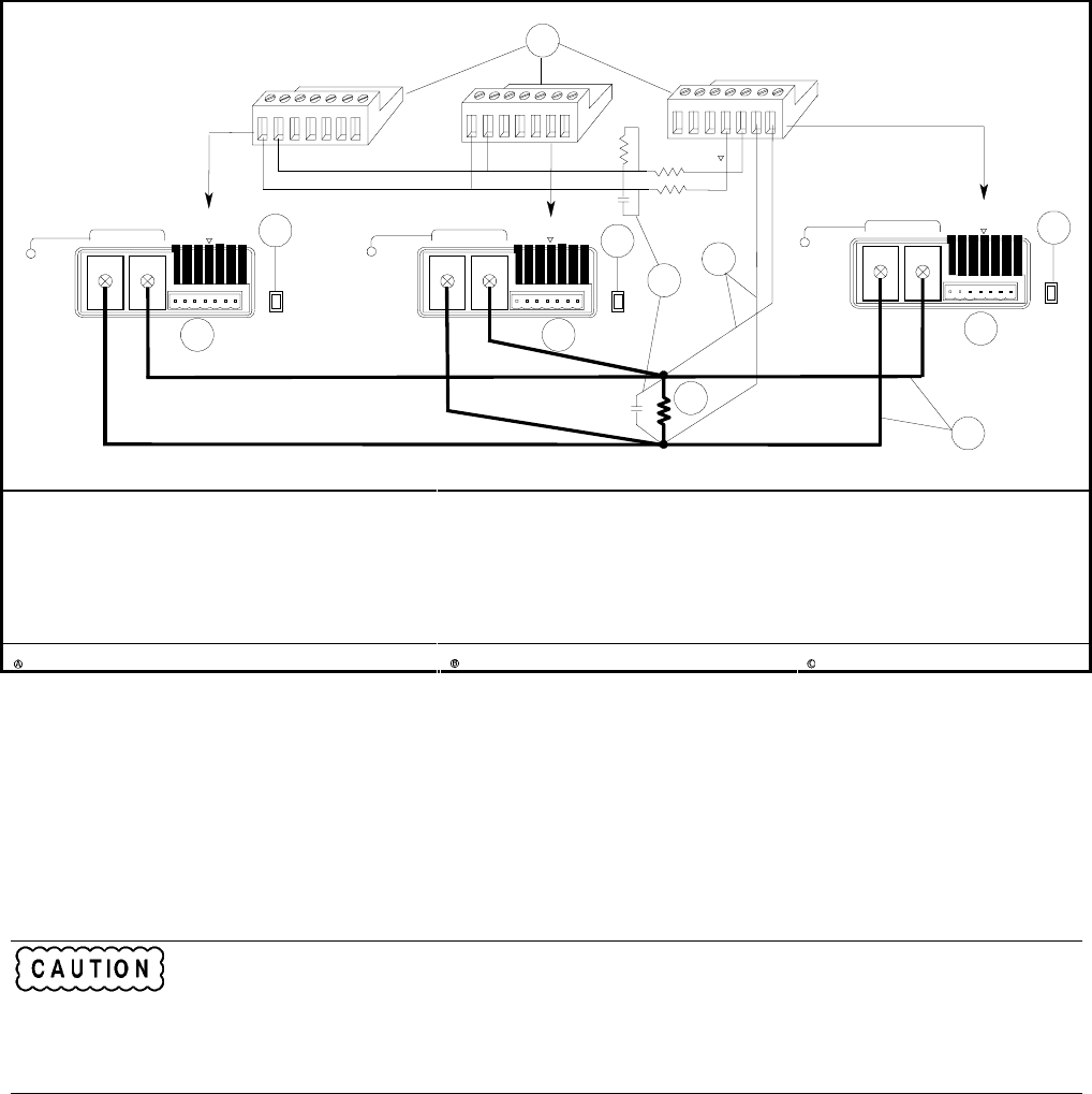
Analog Connectors
ôSlave Supplies
(Set the slave output voltage slightly higher
than the load lead drop to the master to ensure
that the slaves stay in CC mode. Also set the
slave currents to zero.)
③ Master Unit
(Program only the master.)
④ Optional components to reduce
output ringing. (Select only one of the
two methods shown.)
⑤ Load
⑥ Load connection
Set this switch for optional remote sensing Only local sensing permitted Remote sensing connections
Figure 4-8. Auto-Parallel Connection in Fixed Mode (Remote Sensing Optional)
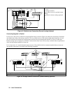
Auto-Parallel Programming in Fixed mode
Program only the first or "master" unit in the series; the current of the "slave" units automatically track the master’s current.
Set the slave unit’s current limit to zero and its voltage and OVP settings higher than the maximum voltage setting of the
master unit. This ensures that the slave supplies will operate in CC mode. Functions such as status, voltage readback, and
current readback can still be read back individually for each unit.
Auto-Parallel Programming Cautions
To avoid possible tripping of the crowbar SCR, do not turn power off on auto-parallel units
while they are operating in Simulator or Table mode. Reprogram all units to Fixed mode and set
the voltage to zero before turning them off.
If a "slave" unit experiences a shutdown condition such as overtemperature or overcurrent, it will not
automatically shut down other units unless you have connected and enabled the remote inhibit (RI) and
discrete fault indicator (DFI) operation. See appendix C and Questionable Status group in chapter 8.
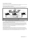
Also use caution when connecting three or more Agilent SAS units for auto-parallel operation because of the OVP crowbar
circuits. If the OVP circuit of any unit trips, its crowbar circuit will draw current from all of the other units. Depending on
the number of units, the additional current may damage the internal SCR of the tripped unit. Use one of the following
techniques to avoid problems.
1. Program the OVP of all slave units to the Maximum Level. This minimizes the chance that the slave OVP circuits
will trip. Then program the OVP level of the master unit to the desired protection level (below the maximum level
specified in table 7-3).
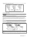
2. Insert Protection Diodes. If you connect all supplies to the load through a series diode (see Figure 4-9) and a unit’s
crowbar SCR trips, it will not draw current from other supplies. Be certain to increase the programmed voltage level of
the slaves by at least 0.7 V to compensate for the voltage drop in the diode.