


User Connections 29
4
User Connections
Rear Panel Connections
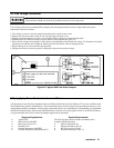
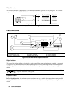
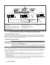
Make application load connections to the output terminals or bus bars, analog connector, and digital connector as shown on
the rear-panel drawing for your model Agilent SAS. Make controller connections (GPIB and serial link) as shown in Figure
4-12 at the end of this chapter.
Wire Selection
Fire Hazard To satisfy safety requirements, load wires must be large enough not to overheat when
carrying the maximum short-circuit current of the Agilent SAS. If there is more than one load, then any
pair of load wires must be capable of safely carrying the full-rated current of the unit.
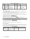
Table 4-1 lists the characteristics of AWG (American Wire Gauge) copper wire.
Table 4-1. Wire Characteristics
AWG No. Ampacity (in free air) Resistance (at 20 deg. C)
Ω/m Ω/ft
20 8.33 0.0345 0.01054
18 15.4 0.0217 0.00663
16 19.4 0.0137 0.00417
14 31.2 0.0086 0.00262
12 40 0.0054 0.00165
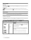
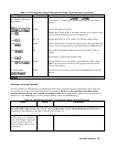
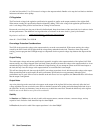
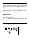
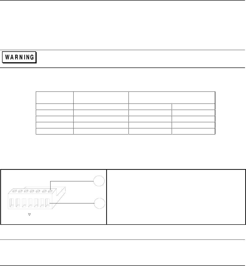
Analog Connector
This connector, which is on the rear panel, is for connecting remote sense leads, external current monitors, and external
current programming sources. The connector accepts wires sizes from AWG 22 to AWG 12.
1
IM
IP
IP
S
S
-
+-
+
-
-
I
SAS
P
2
Insert Wires
k Tighten screws
+IP Differential current programming input (positive).
−
IP Differential current programming input (negative).
−
SAS Auto-parallel output connection (SAS mode only).
Ps Common output for -IM and -SAS signals.
−
IM Current monitor output (referenced to Ps).
+ S remote sense input (positive).
−S remote sense input (negative).
Figure 4-1. Rear Panel Analog Connector
Note It is good engineering practice to twist or shield all signal wires to and from the analog and digital
connectors.
To minimize spurious operation, make sure that all analog wiring except for the + and − sense wires does
not exceed 3 meters in length.