


General Information 15
Output Characteristic
The Agilent E4350B/E4351B Solar Array Simulator can be operated in three modes: fixed mode, simulator mode, and table
mode. Mode switching on the Agilent SAS is accomplished over the GPIB bus via the SCPI CURRent:MODE command.
You cannot switch modes from the front panel.
Note: The Agilent SAS must be connected to a computer for you to be able to use the SAS functions that are
available in simulator and table modes.
The front panel does not indicate which mode the Agilent SAS is presently operating in. If you are unsure which mode the
unit is presently in, you can query the unit over the GPIB using the CURRent:MODE? command. If you cycle power to the
unit, it will be in Fixed mode.
Fixed Mode
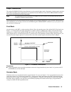
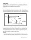
At power turn on, with *RST, or when executing a Device Clear, the operating state of the Agilent SAS is Fixed mode (see
Figure 1-1). In Fixed mode, the output characteristic is similar to that of a standard power supply, except that the output
capacitance is <100 nF on the Agilent E4350B, and <50 nF on the Agilent E4351B. This low output capacitance is ideal
when using the unit as a constant current source. To use the unit as a low-impedance constant voltage source however, you
can add an external output capacitor if so desired. The value of the external capacitor should not exceed 2,000
µ
F.
I
V
set
set
I
V
120V = E4351B
0
E4351B = 4A
480W MAX
MAXIMUM
VOLTAGE
TYPICAL FIXED MODE OUTPUT
MAXIMUM CURRENT
60V = E4350B
E4350B = 8A
Figure 1-1. Fixed Mode Characteristic
Restrictions
■ If the programmed values exceed the maximum current and voltage boundaries by more than 2 or 3 percent, an OUT
OF RANGE error will be indicated.
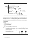
Simulator Mode
Simulator mode uses an exponential model to approximate the I-V curve (see Figure 1-2). It is programmed in terms of its
open circuit voltage (Voc), short circuit current (Isc), voltage point (Vmp), and current point (Imp) at approximately the
peak power point (see page A-9 in appendix A for model equations). Simulator mode operation is achieved by sampling
the output voltage, applying a low-pass filter, and continually adjusting the constant current loop by using the filtered
voltage as an index into the exponential model.