


FORM 100.50-EG3 (802)
63
YORK INTERNATIONAL
*
U
se
S
hielded Wir
e
* Use Shielded Wir
e
*
U
se
S
hielded Wir
e
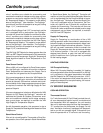
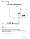
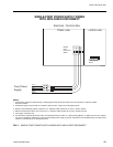
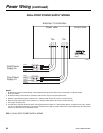
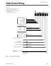
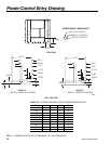
3. Maximum
p
ower available from the 24 VAC
1. Wirin
g
shown indicates typical wirin
g
.
Closed = Smoke Purge
C
losed =
S
hutdow
n
Open = Unoccupied
Closed = Occupied
O
1.5K Ad
j
ust
Si
g
na
l
cause equipment damage.
power source external of the unit may
id
sourced from the unit. Use of another
Note, 24VAC switch volta
g
e must be
df h i U f h
Rela
y
Outpu
t
VAV H
ea
t
Smoke Pur
g
e Inpu
t
Shutdown In
p
u
t
Unoccu
p
ied In
p
u
t
Occu
p
ied
/
to o
p
en full
.
command the VAV boxes
output shall be used to
d h VAVb
Note: VAV Heat Rela
y
hllb d
C
ommo
n
24 VAC Si
g
na
l
Op
en =
N
orma
l
P
o
t
e
nti
o
m
e
t
er
C
ommo
n
0-5V Out
p
u
t
Sensor
C
ommo
n
Si
g
na
l
CO
O
p
en = Norma
l
4.
U
se shielded wire where shown
.
terminal is 4
0
VA
.
2. All wirin
g
is Class 2, low volta
g
e
.
Wirin
g
Notes
:
C
ommo
n
Si
g
na
l
S
p
ace Senso
r
7 Wir
e
Th
e
rmo
s
t
at
G
(
Fan
)
Y2 (Cool Sta
g
e 2
)
Y1 (Cool Sta
g
e 1
)
R
(
24VAC
)
CO
MM
ON
RTD
S
enso
r
1
K
Nickel
I
A
Q
+
CO
M
SS
A+
3
1
2
4
5
S
HIELD
7
9
S
HIELD
1
3
1
5
Y1
CO
M
HR
S
MK
R
(24 VAC)
S
D
OCC
1
8
17
1
9
2
0
21
2
W1
W1 (Heat Sta
g
e 1
)
W2 (Heat Sta
g
e 2
)
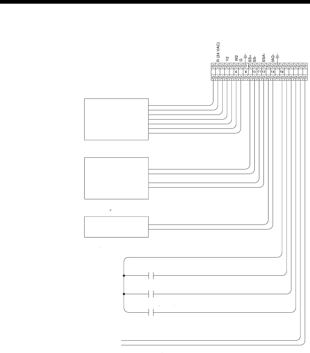
Field Control Wiring
FIG. 4 – FIELD CONTROL WIRING
LD06804