


SCXG-SVX01B-EN 85
Owner
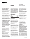
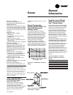
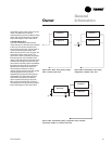
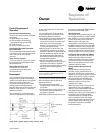
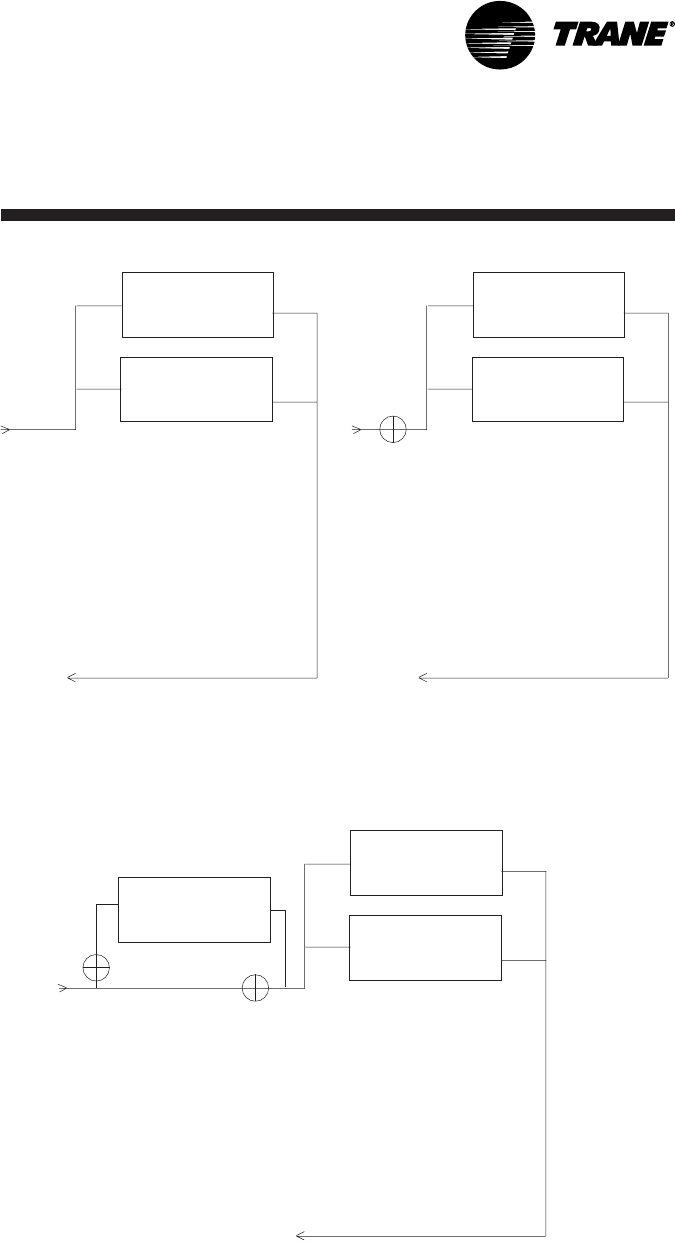
Condenser 1
Condenser 2
V2
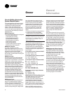
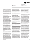
Condenser 1
Condenser 2
V1
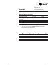
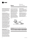
Economizer
Condenser 1
Condenser 2
V2
Figure O-GI-3. Basic water piping configu-
ration, constant water flow.
Figure O-GI-4. Intermediate water piping
configuration, variable water flow.
Figure O-GI-5. Intermediate piping configuration with waterside
economizer, variable or constant water flow.
General
Information
condenser bypass valve closes, and vice
versa. Full water flow is always
maintained through the condensers. Both
valves will close in the event of a power
failure. See Figures O-GI-3 and O-GI-5.
• Variable Water Flow
Two-way modulating control shutoff
valves are wired, controlled, and installed
in the unit. One valve is located in the
economizer’s water inlet, and the other is
in the condenser bypass water inlet.
When the economizer valve is active, the
condenser bypass valve closes. The
economizer valve modulates, thus water
flow through the unit modulates. If the
water is cool enough for economizing, but
mechanical cooling is also required, the
economizer valve fully opens to establish
full water flow through the condensers.
Whenever the water is too warm for
economizing and there is a call for
cooling, the economizer valve fully closes
and the bypass valve fully opens,
establishing full water flow through the
condensers. Full water flow is always
maintained through the condensers
when mechanical cooling is required.
Both valves close whenever cooling is
not required, and in the event of a power
failure. See Figures O-GI-4 and O-GI-5.