


SCXG-SVX01B-EN 53
Note: Guidelines for wire sizes and
lengths are shown in Table I-PR-7. The total
resistance of these low voltage wires
must not exceed 2.5 ohms per conductor.
Any resistance greater than 2.5 ohms may
cause the control to malfunction due to
excessive voltage drop.
Note: Do not run low-voltage control
wiring in same conduit with high-voltage
power wiring.
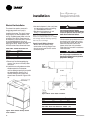
1. Run wires between the unit control
panel and the zone sensor subbase. To
determine the number of wires
required, refer to the unit wiring
diagrams.
2. Connect the wiring to the appropriate
terminals at the unit control panel and
at the zone sensor subbase. In general,
zone sensor connections to the unit use
the convention of connecting zone
sensor terminals to like numbered unit
terminals (1 to 1, 2 to 2, etc.). The
connection detail is shown on the unit
wiring diagrams, which are located in
the unit control panel.
3. Replace the zone sensor cover back
on the subbase and snap securely into
place.
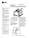
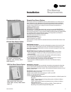
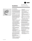
Standard Remote Sensor
(BAYSENS017)
When using the remote sensor,
BAYSENS017, mount it in the space that
is to be controlled. Wire according to the
interconnecting wiring diagrams on the
unit.
Table I-PR-7. Zone Sensor Maximum
Lengths and Wire Size
Distance from Recommended
Unit to Controller Wiring Size
0-150 feet 22 gauge
151--240 feet 20 gauge
241-385 feet 18 gauge
386- 610 feet 16 gauge
611-970 feet 14 gauge
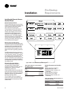
Pre-Startup
Requirements
Zone Sensor Installation
All sensor options ship in the main control
panel and are field-installed.
Programmable option installation
procedures are on page 55.
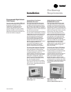
Mounting Location
Mount the sensor on the wall in an area
with good air circulation at an average
temperature. Avoid mounting space
temperature sensor is areas subject to
the following conditions:
• Drafts or “dead” spots behind doors or
in corners
• Hot or cold air from ducts
• Radiant heat from the sun or appliances
• Concealed pipes and chimneys
• Unheated or non-cooled surfaces
behind the sensor, such as outside walls
• Airflows from adjacent zones or other
units
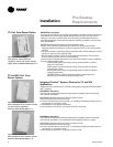
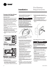
To mount the sensors, remove the dust
cover and mount the base on a flat
surface or 2" x 4" junction box. Sensors
ship with mounting screws.
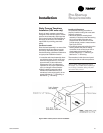
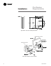
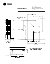
Mounting the Subbase
Remove the zone sensor cover from
subbase, and mount subbase on the wall
or on a 2 x 4 junction box. Route wires
through the wire access hole in the
subbase. See Figure I-PR-22 on page 54.
Seal the hole in the wall behind the
subbase.
Wiring
Disconnect all electric power
including remote disconnects
before servicing. Failure to do so
before servicing may cause severe
personal injury or death.
Figure I-PR-21. Standard zone sensor,
BAYSENS017, ships with all units.
ƽƽ
ƽƽ
ƽ
WARNING
!
Installation