


SCXG-SVX01B-EN 57
Pre-Startup
Requirements
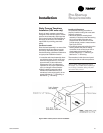
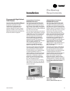
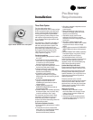
Time Clock Option
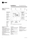
The time clock option has a
programmable timer that is factory wired
to the unoccupied input to provide on/off
control. The time clock will not allow the
unit to pass through the night setback/
morning warmup mode, except on units
with optional night heat/morning warm
up, or programmable night setback. See
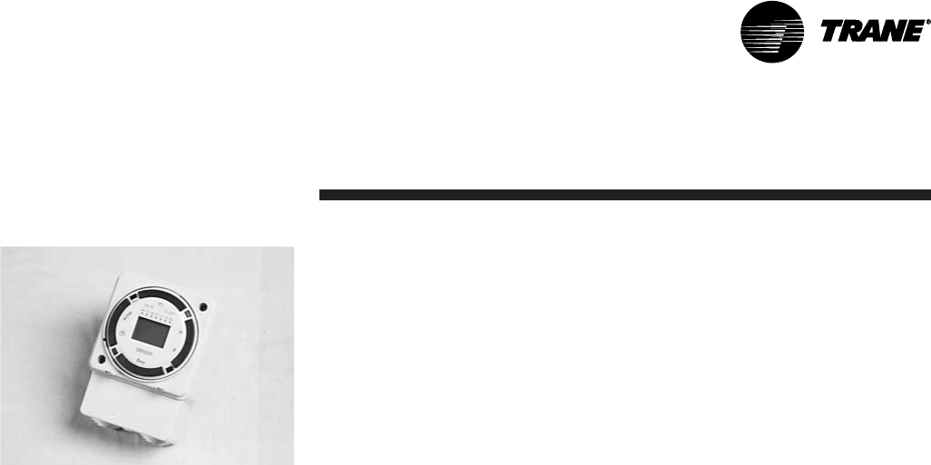
Figure I-PR-30.
The timeclock, a “Digi 20” by Grasslin, is
inside the control panel, but accessible
with the control panel door closed. This
same type timer is also used for pro-
grammable night setback/morning warm
up. Programming instructions for the
“Digi 20” timer are in the “Program-
ming” section on page 73.
Timeclock Installation
1. Ensure operating temperature is within
4 to 131 F.
2. Locate the time clock at least 5 feet
away from any large electrical contact
or machinery to avoid possible
electrical interference problems.
3. Provide a separate independent circuit
for the time clock power supply.
4. Since all electronic instruments are
sensitive to voltage spikes, pay close
attention tot he following:
a. If possible, supply power to the
electronic time clock from a phase
different than the one supplying power
to the load.
b. Provide a suitable Varistor or RC
network across the INDUCTIVE
LOADS supply terminals to reduce
voltage spikes.
c. Place a diode across the DC
OPERATED INDUCTOR terminals to
eliminate back EMF.
d. HIGHLY INDUCTIVE LOADS, especially
fluorescent lights, may require a relay
in which case step a. and c. apply.
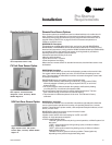
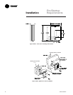
The timeclock can be surface or flush
mounted. Lift off the front cover and
loosen the two screws on opposite
corners. Pull off the base’s plug with a left
to right rolling motion.
Timeclock Installation Checklist
1. Ensure operating temperature is within
4 to 131 F.
2. Locate the time clock at least 5 feet
away from any large electrical contact
or machinery to avoid possible
electrical interference problems.
3. Provide a separate independent circuit
for the time clock
power supply.
4. Since all electronic instruments are
sensitive to voltage spikes, pay close
attention to the following:
a. If possible, supply power to the
electronic time clock from a phase
different than the one supplying power
to the load
b. Provide a suitable Varistor or RC
network across the INDUCTIVE LOADS
supply terminals to reduce voltage
spikes.
c. Place a diode across the DC OPERATED
INDUCTOR terminals to eliminate back
EMF.
d. HIGHLY INDUCTIVE LOADS, especially
fluorescent lights, may require a relay
in which case (A) and (C) apply.
The Digi 20A timeclock unit can be
surface or flush mounted. Lift off the front
cover and loosen the two screws on
opposite corners. Pull off the base’s plug
with a left to right rolling motion.
Surface Mounting Inside Panel
Place screws through the base’s preset
holes and screw to back of panel or wall.
Wire according to the instructions in the
following section. Depending upon the
specific installation, you may find it more
convenient to complete wiring before
attaching the base.
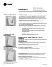
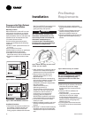
Place the terminal cover over the
terminal block by aligning the two screws
with the corner holes in the base. Push
the timer firmly onto the plug in the base.
Tighten the two screws. A base for DIN
rail mounting is optional.
Wiring the Timeclock
1. Wire 24, 120, or 220 VAC to input
terminals. Make sure to apply correct
voltage. Using incorrect voltage will
void the warranty.
2. Connect wire to the screw terminals
according to the unit wiring diagrams.
Use 12 to 22 AWG wire.
Figure I-PR-30. Grasslin time clock option.
Installation