


SCXG-SVX01B-EN 35
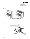
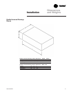
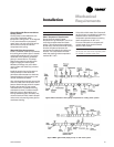
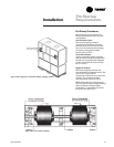
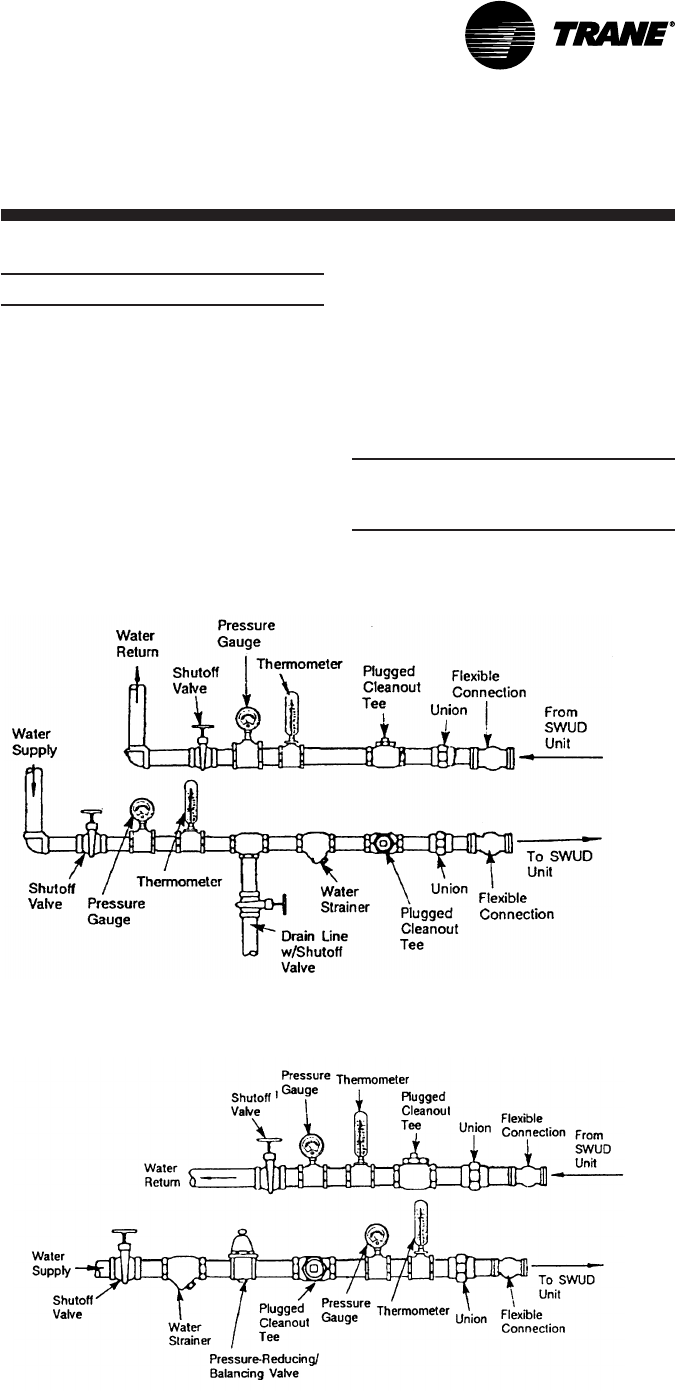
Figure I-MR-3. Condenser water piping components for cooling tower system.
Mechanical
Requirements
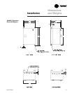
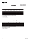
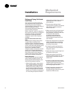
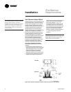
Figure I-MR-4. Typical water piping for city or well water system.
Installation
General Waterside Recommendations:
Cooling Towers
Cooling tower control affects the unit
cycle rates. Condenser water
temperature swings from 10-15 degrees
F may cause excessive compressor,
water valve, and unit cycling. Be sure to
set the tower controls to minimize
compressor/unit cycling.
Waterside Piping Arrangements
Install a condenser water pump between
the cooling tower (either open or closed)
and the self-contained unit. Lay out the
remainder of the system’s condenser
piping in reverse returns. This helps
balance the system by equalizing the
length of supply and return pipes.
Multistory buildings may use a direct
return system with balancing valves at
each floor.
Install the supply riser and its return in
close proximity. Furnish both with
permanent thermometers to check the
waterside balance during start-up and
routine maintenance checks.
Also, include strainers at each pump inlet
and unit. Install drain valves at the riser’s
base to allow drainage points for system
flushing during start-up and routine
maintenance. For condenser draining
and header removal, include a shutoff/
balancing valve on the entering and
leaving waterside pipes, drain tees, and
unions of each unit. Also, install a shutoff
valve on the unit entering water pipe for
condenser draining.
Note: Unit does not have floor drains.
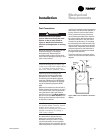
Water Temperature Requirements
Do not allow the entering water
temperature to go below 54 F (12.2 C) on
units with constant water flow (basic
piping). This will cause the compressors
to shut down and the mechanical cooling
function will lockout. However, the
economizer (if enabled) will continue to
function. The compressors will reset
when the entering water temperature
reaches 58 F (15C).
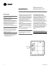
Units with variable water flow (intermedi-
ate piping) have a modulating condensing
pressure control valve that allows
compressor operation down to entering
water temperatures of 35 F (2 C).
For more information on constant and
variable water flow, see the Owner’s
section of this manual.
Note: Units with a waterside economizer
can be set from the human interface panel
for variable or constant water flow.