SCXG-SVX01B-EN 51
Pre-Startup
Requirements
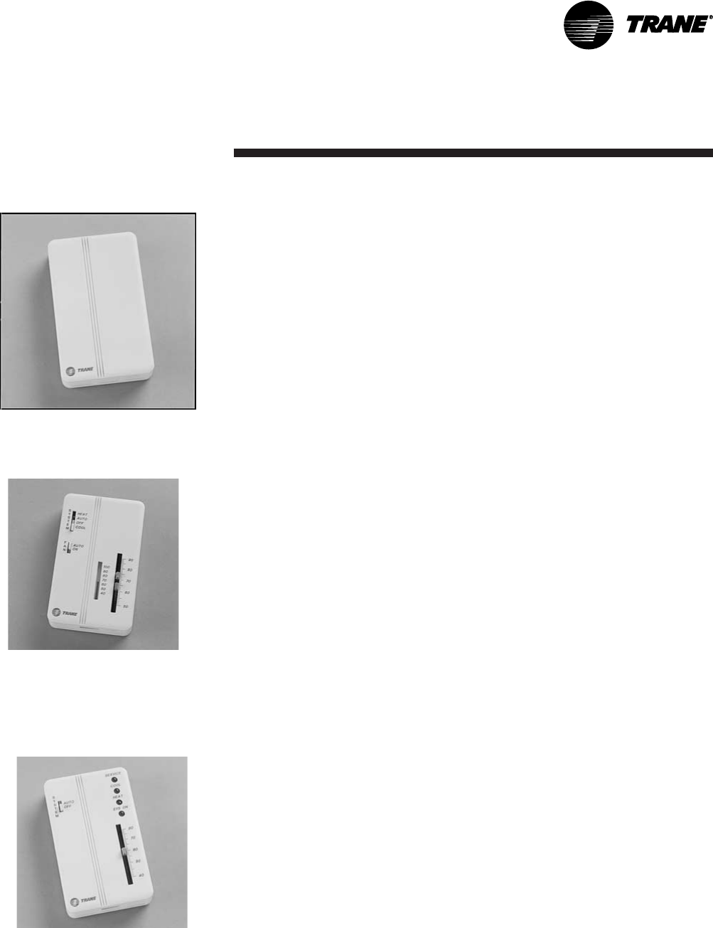
Figure I-PR-15. BAYSENS017
Zone Temperature Sensor Only
Standard with All Units
Remote Zone Sensor Options
Zone sensor options are available and can be ordered with the unit or after the unit
ships. Following is a full description of zone sensors and their functions. Installation
instructions are on page 53. Instructions for the programmable zone sensor are on
page 55. Refer to Table O-GI-2 on page 79 for the zone sensor temperature vs.
resistance coefficient curve.
BAYSENS017B Description
This zone sensor module ships with all units, and can be used with BAYSENS019,
BAYSENS020, or BAYSENS021 remote sensors. When this sensor is wired to one of
these remote zone sensors, wiring must be 18 AWG shielded twisted pair (Belden 8760
or equivalent). Refer to the specific zone sensor for wiring details. It provides the
following features and system control functions:
• Remote temperature sensing in the zone
• Morning warmup sensor
• Zone sensor for ICS™ systems
• Zone temperature averaging
When used as a remote sensor for standard zone sensor, the thermistor sensor must
be disabled.
Figure I-PR-17. BAYSENS021
Single setpoint sensor with system
function lights, Accessory Model Number
Digit 6 = H
BAYSENSO21 Description
This zone sensor module is for use with VAV units without night setback. It allows the
user to control system operation and monitor unit operating status from a remote
location. The sensor has a system switch, a S/A temperature setpoint indicator, a local
sensor, and four LED’s.
BAYSENSO21 features and system control functions include:
• Temperature sensing in the zone
• System control switch with mode setting for "AUTO" and "OFF"
• Supply air single temperature setpoint
• Function status indicator lights:
“SYS ON” glows continuously during normal operation, or blinks if system is in
test mode.
“COOL” glows continuously during cooling cycles, or blinks to indicate a
cooling system failure.
“HEAT” glows continuously during heating cycles, or blinks to indicate a
heating system failure.
“SERVICE” blinks or glows to indicate a problem. These signals vary
depending on the particular equipment being used.
VAV Unit Zone Sensor Option
CV Unit Zone Sensor Option
Figure I-PR-16. BAYSENS008
Dual setpoint, manual/automatic
changeover sensor, Accessory Model
Number Digit 6 = E
BAYSENS008 Description
This zone sensor module is for use with cooling/heating constant volume units. It has
four system switch settings (heat, cool, auto, and off) and two fan settings (on and
auto). The zone sensor provides either manual or automatic changeover control with
dual setpoint capability.
BAYSENS008 features and system control functions include:
• System control switch to select heating mode (HEAT), cooling mode (COOL),
automatic selection of heating or cooling as required (AUTO), or to turn the
system off (OFF).
• Fan control switch to select automatic fan operation while actively heating
or cooling (AUTO), or continuous fan operation (ON).
• Dual temperature setpoint levers for setting desired temperature. The blue
lever controls cooling, and the red lever controls heating.
• Thermometer to indicate temperature in the zone. This indicator is factory
calibrated.
Installation


