


SCXG-SVX01B-EN 45
Pre-Startup
RequirementsInstallation
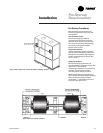
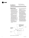
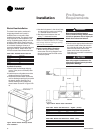
Hydronic Coil Installation
These instructions are for steam and hot
water coil installation. The hydronic coil
assembly has a full coil, piping, a modu-
lating temperature control valve, and a
disc temperature limit device located in
the unit near the fan on the motor frame.
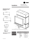
Hydronic coils are available with either
right or left-hand pipe connections. Piping
connections are identical to the unit
piping. For example, if you have right-
hand unit piping, the hydronic coil will
have right-hand connections. The
hydronic coil assembly has temperature
controls to keep the unit’s internal cabinet
temperature below 105 F to prevent
motor and bearing damage.
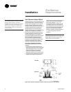
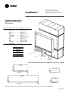
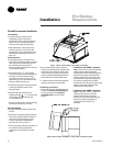
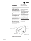
Installation Procedure
1. Remove filter rack from the back of the
unit. Remove the
1
/
4
-inch hex head
screws from the top and bottom of the
filter rack assembly. The filter rack
assembly will hang on the unit when
the screws are removed. The filter rack
can now be removed by lifting up on
the filter rack.
2. Remove the hydronic coil from the
crate and position it behind the unit with
the open side facing the unit evaporator
coil inlet. Also, remove the plastic
envelope that is taped to the coil box
assembly. This envelope contains the
mounting screws needed to attach the
coil box to the unit and the gasket
required on the vertical side flanges of
the box.
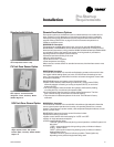
3. Install the pressure sensitive gasket to
the unit side of the vertical flange on the
coil box in two places.
4. Using 2” x
1
/
2
” standard thread
eyebolts, thread into the coil lift plates to
raise the coil up to the height necessary
to attach it to the unit. The top panel has
a “J” hook on it to allow hanging,
similar to the filter rack. Align the holes
so that the coil hangs on the unit. If the
unit has the dirty filter option, connect
the static pressure tube to the unit
before bolting the coil in place. Locate
the static pressure tubing on the unit
evaporator coil and route through the
knockout in the top corner of the coil
box.
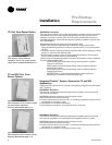
5. Align the hydronic coil with the holes in
the unit channel or waterside
economizer option. Move the coil box
up against the unit and install using six
mounting screws in the top and six in
the bottom of the coil box.
6. Remove the valve and pipe cover on
the coil box. Connect the wires that are
coiled in the coil box, referring to the
wiring diagram installed on the unit
control panel door. Route wires into the
unit through knockouts in the top of the
box.
7. Reinstall the filter rack on the back of
the heating coil rack. If the unit has the
waterside economizer option, the filter
rack will require additional support legs.