


56 SCXG-SVX01B-EN
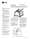
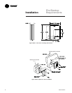
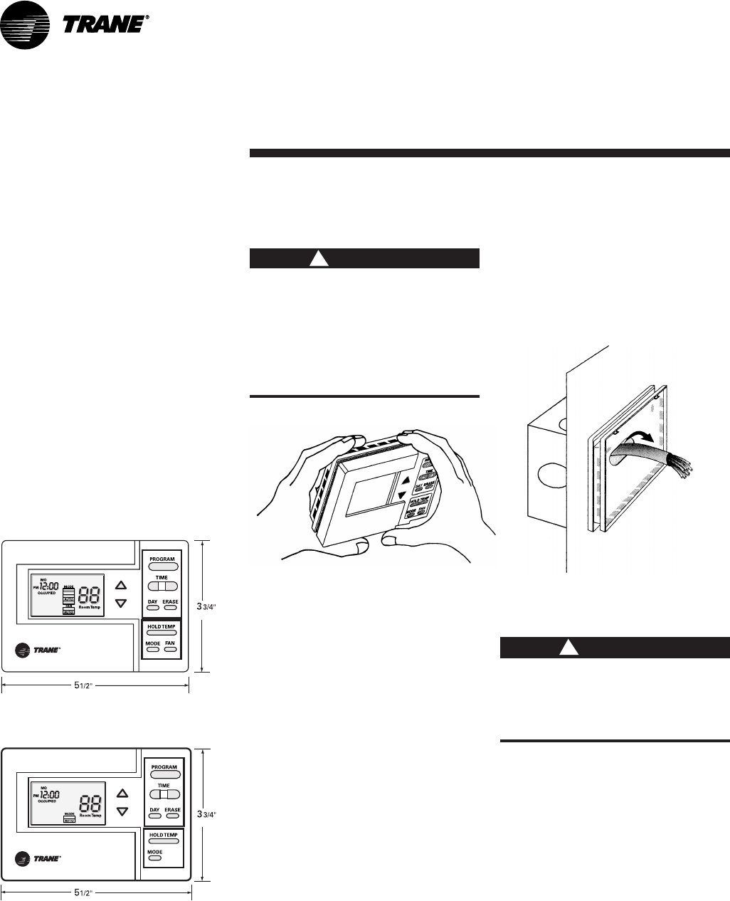
6. Pull the zone sensor module wires
through the subbase as shown in Figure
I-PR-31.
7. Loosely secure subbase to the wall
with the mounting screws. Do not
tighten the subbase screws yet.
8. Level the subbase by sight, then firmly
tighten the three subbase mounting
screws.
Do not overtighten the subbase
screws. Overtightening may
cause the screws to crack the
subbase.
9. Before wiring the subbase, identify the
wires from the unit’s low voltage
terminal strip. Each screw terminal is
labeled.
10. Remove TB from subbase and
discard the tape.
11. Strip the wires
1
/
4
” and
connect the
wires from the unit’s low voltage
terminal strip to the zone sensor
module subbase. Reference connection
details on the unit wiring diagrams,
located on the unit.
12. Firmly tighten each screw terminal.
13. Fit the wires as close to the subbase
as possible.
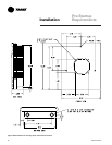
Pre-Startup
Requirements
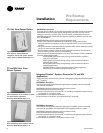
Programmable Night Setback
Zone Sensor Installation
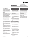
Mounting Location
Mount the sensor on the wall in an area
with good air circulation at an average
temperature. Choose a location that is
easily accessible, and on a wall where the
subbase can be mounted about 5 feet
(1.5 meters) above the floor.
Avoid mounting space temperature
sensor is areas subject to the following
conditions:
• Drafts or “dead” spots behind doors or
in corners
• Hot or cold air from ducts
• Radiant heat from the sun or appliances
• Concealed pipes and chimneys
• Unheated or non-cooled surfaces
behind the sensor, such as outside walls
• Airflows from adjacent zones or other
units
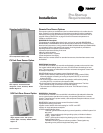
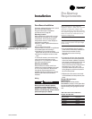
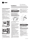
(140 mm)
(95 mm)
(140mm)
(95mm)
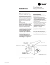
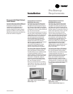
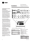
Installation Procedure
1. Remove the zone sensor module from
the subbase. Carefully hold the zone
sensor module with one hand and
firmly grasp the subbase with the other.
See Figure I-PR-27. To remove the zone
sensor module from the subbase,
gently pull away and upward.
The zone sensor module is an
electronic sensitive device. Do
not touch printed circuit board,
electronic components, or
connector pins. Handle plastic
housing only to prevent damage
to electronic components.
2. After disassembly, protect the internal
surfaces from contact with objects or
substances that could cause damage.
3. Remove the terminal block from
subbase and set aside for wiring.
Discard the tape.
4. Mount the zone sensor module using
the mounting hardware included in the
shipping package. The mounting
hardware is contained in single plastic
bag and includes:
• Plastic wall anchors (3 x)
• Mounting screws (3 x)
The zone sensor module can mount
directly to a wall or to a junction box
mounted to a wall. To mount to a
junction box, you must have the
mounting plate and adapter kit,
BAYMTPL003. Installation instructions
are enclosed with the mounting plate.
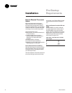
5. To mount the zone sensor module
directly to a wall:
a. Hold the subbase in position and mark
the three mounting hole locations on
the wall.
b. Drill three
3
/
16
” (4.8 mm)
holes. Gently tap
the plastic wall anchors into the holes
until the anchor tops are flush with the
wall.
Figure I-PR-29. Securing the subbase.
Figure I-PR-28. Removing the zone sensor
module from the subbase.
ƽƽ
ƽƽ
ƽ
CAUTION
!
ƽƽ
ƽƽ
ƽ
CAUTION
!
Installation
Figure I-PR-26. BAYSENS019 dimensions.
Figure I-PR-27. BAYSENS020 dimensions.