


10 SCXG-SVX01B-EN
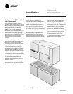
Installation
Pre-Installation
Considerations
Installation Preparation
Before installing the unit, perform
the following procedures to
ensure proper unit operation.
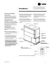
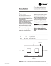
1. Verify the floor or foundation is level.
Shim or repair as necessary. To ensure
proper unit operation, install the unit
level (zero tolerance) in both horizontal
axis. Failure to level the unit properly
can result in condensate management
problems, such as standing water
inside the unit. Standing water and wet
surfaces inside units can result in
microbial growth (mold) in the drain
pan that may cause unpleasant odors
and serious health-related indoor air
quality problem.
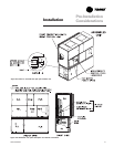
2. Allow minimum recommended
clearances for maintenance and
routine service. See “Service Access”
section on page 11.
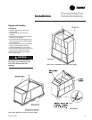
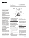
3. Position the unit and skid assembly in
its final location. If unit shipped split-
apart, follow the procedure in the
“Split-Apart Unit Assembly” section
on page 14 before completing this
step. Test lift the unit to determine
exact unit balance and stability before
hoisting it to the installation location.
See Figure I-PC-7 and I-PC-8 on page
13 for typical rigging procedures,
including cautions and proper uses of
such equipment as fork lifts, spreader
bars, and hooks.
4. Remove the skids from under the unit.
See the “Rigging and Handling”
section on page 12. Refer to the “Skid
Removal” section on page 16. If you
find internal damage, file a claim
immediately to the delivering carrier.
5. Remove the protective shipping covers
from the unit. Refer to the “Unit
Protective Covers” section on page 39.
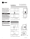
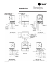
Note: Unit height and connection locations
will change if external vibration isolators
are used. The unit may be raised an
additional 5
7
/
8
inches with spring-type
isolators.
Note: Unit height and connection locations
will change if the unit is constructed to be
split-a-part in the field. See unit submittal
drawings for connection locations.
6. Electrical supply power must meet
specific balance and voltage
requirements, as described in the
“Electrical Requirements” section on
page 37.
7. Water-cooled units only (model
SXWG): The installer must furnish and
install a condenser main and standby
water pump, cooling tower, pressure
gauges and all components for the
waterside piping. See the “Water
Piping” section on page 34 for general
waterside recommendations.
8. Air-cooled units only (model SXRG):
These units require field-installation of a
remote air-cooled condenser and
refrigerant piping. See the “Refrigerant
Piping” section on page 36 for general
piping recommendations.