


Form RZ-NA-I-LDAP, P/N 207733 (Rev 2), Page 9
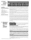
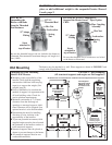
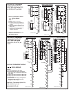
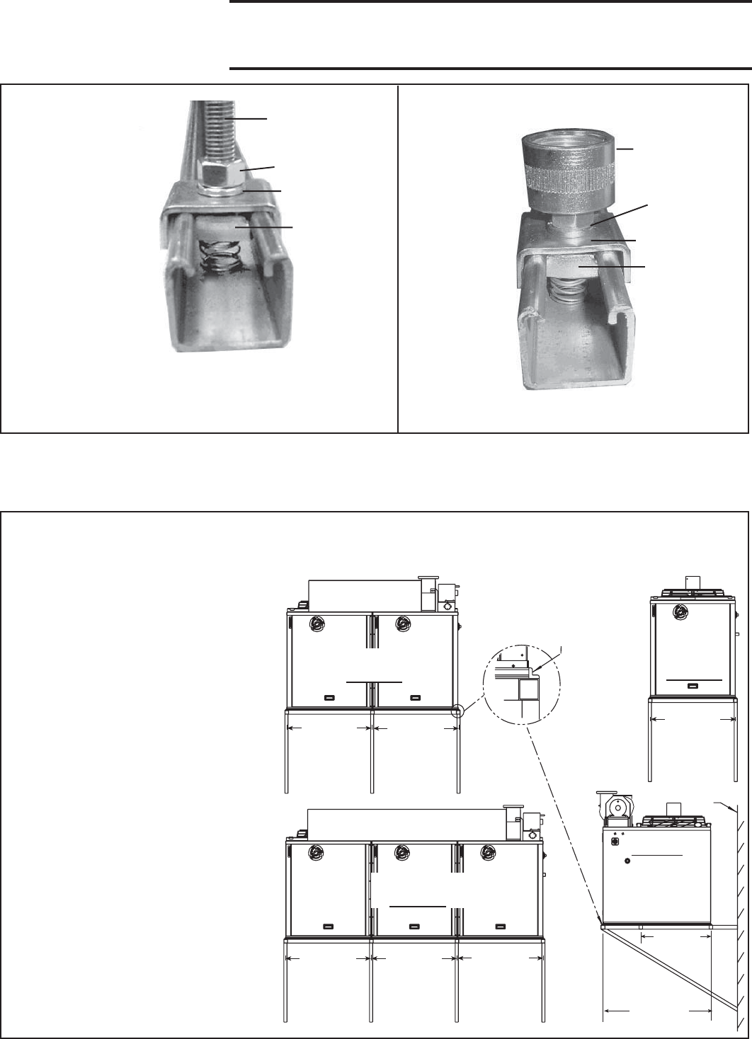
FIGURE 4B- Swivel Connectors to
Suspend the Heater from 1” Pipe, Option
CK10
Be sure the threaded swivel connectors are locked
to the heater as illustrated.
WARNING: All heaters must be level for proper operation. Do not
place or add additional weight to the suspended heater. Hazard
Levels, page 2.
Be sure the threaded hanger rods are locked to the heater as
illustrated. Recommended maximum hanger rod length is 6
feet (1.8M).
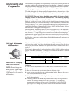
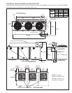
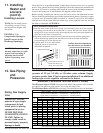
The heater may be attached to a wall. Place supports as shown in FIGURE 5 and
comply with all guidelines listed.
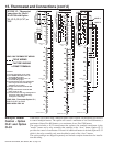
FIGURE 5 - Wall Mounting
(All structural supports and angles are field supplied.)
Wall Mounting
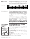
Guidelines for Wall Mounting
Model LDAP Heaters
Mounting is the responsibility of the
installer. Verify that the supporting
structure has sufficient load-carrying
capacity to support the weight. (See
weights, page 8.)
Prior to installation, be sure that the
method of support is in agreement with
all local building codes. Check for
service platform requirements.
Maintain a minimum of 2” (51mm)
clearance from the discharge air
openings to structural supports. Addi-
tional clearance will be required if an
optional nozzle is to be field installed.
Determining the need for installing
vibration or noise isolation is the
responsibility of the installer.
To prevent potential movement, field-
supplied angles must be placed around
the perimeter of the heater to anchor it
to the structural supports.
Structural supports must be placed as
shown to prevent damage to the heater.
All structural supports must be non-
combustible materials.
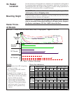
Strut
attached to
top of heater.
1/2”-13
Threaded Rod
Hex Nut
Lockwasher
“U”-shape
Fitting
Spring
Nut
Strut
attached to
top of heater.
Lockwasher
“U”-shape
Fitting
Hex Nut
Pipe Coupling
Assembly
Spring
Nut
Field-Supplied
Mounting Angles
(MUST be on all
four sides of the
heater.)
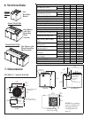
Model LDAP 800
(2 heat sections)
Front View
Model LDAP 1200
(3 heat sections)
Front View
Model
LDAP 400
(1 heat
section)
Front View
Side View
Dimensions are
centerline of the
mounting angles
and apply to all sizes.
Wall
34-33/64
(877mm)
34-33/64
(877mm)
34-33/64
(877mm)
34-43/64
(881mm)
34-33/64
(877mm)
34-11/32
(872mm)
28-1/4
(718mm)
42-1/2
(1080mm)
All dimensions are measured from centerlines of field-supplied structural supports.
FIGURE 4A -
Suspending the
Heater with Rods
from the Threaded
Nut Retainers