


Form RZ-NA-I-LDAP, P/N 207733 (Rev 2), Page 22
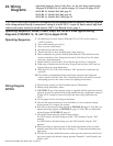
Operating Sequence
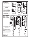
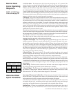
Wiring Diagram
NOTES
1. Set thermostat at lowest setting. With Opt CL2 or CL18, set fan switch at
“AUTO” position.
2. Turn on the manual gas valve(s).
3. Turn on power to the heater.
4. Set thermostat at desired setting.
5. Thermostat calls for heat, energizing the venter motor(s).
6. Main combustion air pressure switch (Sizes 800 and 1200) and heat section
pressure switch(es) close, firing heat section(s) (Unit fires at low fire when
using two-stage thermostat).
7. Burner flame is sensed, and in 30 seconds the fan motor(s) is energized.
8. High stage of thermostat calls for heat, firing all heat sections at full rate (on
heaters with a two-stage thermostat).
9. With Opt CL2 or CL18, set fan switch at “ON” position for continuous fan
operation.
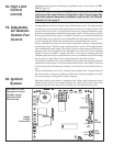
10. If the flame is extinguished during main burner operation, the integrated
control system closes the main valve of that heat section and must be reset by
interrupting power to the control circuit (see lighting instructions).
1. The following controls are field-installed options: Thermostat
2. Dotted wiring installed by others.
3. CAUTION: If any of the original wiring as supplied with the appliance must be
replaced, it must be replaced with wiring material having a temperature rating of
at least 105°C, except for sensor lead wire and limit wiring which must be
150°C.
4. Use 18 gauge wire for all wiring on the heater.
5. Line and fan motor branch wire sizes should be of a size to prevent voltage
drops beyond 5% of supply line voltage.
6. Size 400, see thermostat wiring diagram in FIGURE 10, page 15. Size 800, see
thermostat wiring diagram in FIGURE 11, page 15. Size 1200, see thermostat
wiring diagram in FIGURE 12, page 16.
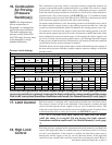
7. The control transformer has a dual voltage primary.
For 230V heaters, the black lead goes to the “240” terminal. Cap the “208”
terminal.
For 208V heaters, the black lead goes to the 208” terminal. Cap the “240”
terminal.
8. When providing or replacing fuses in the fusible disconnect switch, use dual
elements time delay fuses and size according to 1.25 times the maximum total
input amps.
9. The line side of the lockable disconnect switch must be connected to the incom-
ing power supply such that the voltage between Terminal L1 and Ground is the
greater value.
Operating Sequence, Notes, Codes, Keys, etc for ALL three typical wiring
diagrams (FIGURES 14, 15, and 16) on pages 23-25.
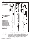
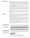
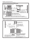
23. Wiring
Diagrams
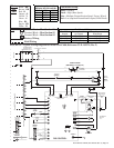
• Operating Sequence, Notes, Codes, Keys, etc. for ALL three typical wiring
diagrams (FIGURES 14, 15, and 16 on pages 23, 24, and 25), pages 22-23.
• FIGURE 14 - Model LDAP 400, page 23.
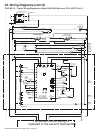
• FIGURE 15 - Model LDAP 800, page 24.
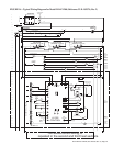
• FIGURE 16 - Model LDAP 1200, page 25.
CAUTION: If any of the original wire as supplied with the appliance must be replaced, it must be replaced
with wiring material having a temperature rating of at least 105°C, except for limit control, high limit
control, and sensor lead wires which must be 150°C. See Hazard Levels, page 2.