Form RZ-NA-I-LDAP, P/N 207733 (Rev 2), Page 3
4. Uncrating and
Preparation
This heater was test operated and inspected at the factory prior to crating and was in
operating condition. If the heater has incurred any damage in shipment, document
the damage with the transporting agency and contact an authorized Reznor Distribu-
tor. If you are an authorized Distributor, follow the FOB freight policy procedures as
published by Thomas & Betts for Reznor products.
Check the rating plate for the gas specifications and electrical characteristics of the
heater to be sure that they are compatible with the gas and electric supplies at the
installation site.
I
MPORTANT: The crate bottom should be removed after the heater is lifted.
Shipping brackets are attached with cabinet screws. When removing shipping
brackets, re-insert ALL screws into the cabinet.
Read this booklet and become familiar with the installation requirements of your
particular heater. If you do not have knowledge of local requirements, check with the
local gas company or any other local agencies who might have requirements con-
cerning this installation. If the installation is above 2000 ft (610M) elevation, follow
the instructions in Paragraph 5 and Paragraph 12.
Before beginning, make preparations for necessary supplies, tools, and manpower.
Locate the hardware kit supplied with the heater. The plastic bag contains spring
nuts, hex nuts, “U”-shape fittings, lock washers, louvers, and compression springs.
Be sure that all shipped-separate options that were ordered are at the installation site.
Shipped-separate items could include a vent cap, louvers, nozzles, hanger kit, a manual
shutoff valve, a thermostat, multiple heater controls, high temperature tape, and/or a
high altitude kit.
If the heater is being installed at an elevation above 2000 ft (610M), the input rate
will have to be derated. This is done by adjusting the outlet pressure of the gas valve
and can only be done after the heater is in operation. Follow the instructions in Para-
graph 12.
If the heater is being installed at an elevation above 6000 ft (1830M), the heat section
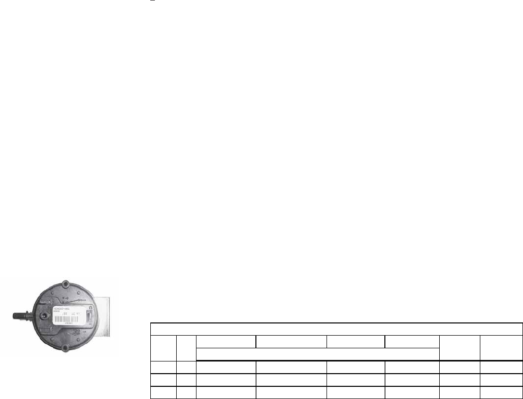
pressure switch(es) will need to be changed. If ordered with the heater as Option
DJ20, the pressure switch is shipped separately.
5. High Altitude
Operation
Instructions for Changing
Heat section Pressure
Pressure Switch
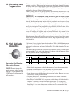
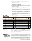
Start-up Cold Equilibrium Hot Setpoint OFF Setpoint ON
400 1 1.75 to 1.45 1.00 to 0.80 0.60 0.78 Lt. Blue 197029
800 2 1.85 to 1.55 1.05 to 0.85 0.60 0.78 Lt. Blue 197029
1200 3 2.35 to 1.85 1.50 to 0.95 0.60 0.78 Lt. Blue 197029
Label
Color
Switch
Part No.Differential Pressure (in. w.c.)
High Altitude Unit Pressure Switch(es)
QtySize
Switch(es)
1. In the control compartment of the first heat section, locate the pressure switch.
2. Mark and disconnect the two wires attached to the pressure switch.
3. Mark and disconnect the sensing tubes from the pressure switch.
4. Locate the two screws holding the switch mounting bracket. Remove the screws
(save screws) and the pressure switch.
5. Using the same screws, install the high altitude pressure switch. Attach the
sensing tubes and wires.
6. If installing a Model LDAP 400, the pressure switch change for high altitude is
complete. If installing a Model LDAP 800, repeat Steps 1-5 to change the
pressure switch on the second heat section. If installing a Model LDAP 1200,
repeat Steps 1-5 to change the pressure switches on the second and third heat
sections.
NOTE: Do not change the
main pressure switch located
on top of a Size 800 and Size
1200 heater. It is the same for
all elevations.


