


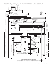
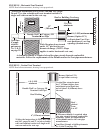

Form RZ-NA-I-LDAP, P/N 207733 (Rev 2), Page 38
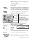
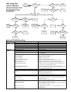
The integrated circuit board monitors the operation of the heater and includes two
LED signal lights that indicate normal operation and various abnormal conditions. If
the heater fails to operate properly, check this signal to determine the cause and/or to
eliminate certain causes. See operating sequence in Paragraph 19.
Do not attempt to repair the DSI integrated control module; the only field replaceable
component is the fuse.
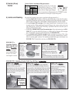
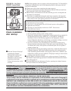
Check the Lights on
the DSI Integrated
Control Module
(Circuit Board)
IMPORTANT: When using a
multimeter to troubleshoot the
24 volt circuit, place the meter’s
test leads into the 5 or 9 pin
connectors located on the
ignition control. Do not remove
connectors or terminals from
the electrical components.
Doing so can result in misinter-
preted readings due to the
ignition control board’s fault
mode monitoring circuits.
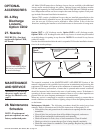
43. Troubleshooting
Steady On Normal Operation - No call for heat. Steady On Flame is sensed.
Fast Flash Normal Operation - Call for heat. Slow Flash Weak flame (current below
1.0 microamps ±50%)
1 Flash System Lockout (failed to detect or
sustain flame)
Fast Flash
2 Flash Main combustion air pressure
switch or heat section pressure
switch does not close with 30
seconds of venter being energized.
3 Flash Limit or high limit switch open.
4 Flash Main combustion air pressure
switch or heat section pressure
switch is closed before venter is
energized.
Steady Off Blown fuse; No power; or Defective
board
Undesired flame (valve
open and no call for heat).
Control Status - GREEN LED Codes Flame Status - YELLOW LED Codes
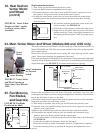
40. Transformer
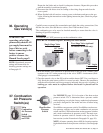
See FIGURE 22, page 34, for location. Use a voltmeter to verify
that there are 24 volts output from the transformer. If the trans-
former is not functioning, it must be replaced. Use a replacement
transformer identical to the factory-installed model.
39. High Limit
Control
A manual reset high limit control is located at the top of each heat
section. Do not reset high limit control without correcting the prob-
lem. If it is determined that the limit control needs replacing, use
only a factory-authorized replacement part that is designed for the
size of heater.
42. Vent System
Check the complete vent system at least once a year. Inspection should include all
joints, seams, and the vent terminal cap. Clean openings. Replace any defective parts.
41. Adjustable
Fan Control
See FIGURE 22, page 34, for location. Check the wiring connec-
tions and the adjustment knob.
If it is determined that the destratification fan control needs re-
placing, use only a factory-authorized replacement part that is de-
signed for the heater.
38. Limit
Control
If it is determined that the automatic reset limit control needs re-
placing, use only a factory-authorized replacement part that is de-
signed for the size of heater.
For approximate limit location, see FIGURE 22, page 34.