


Form RZ-NA-I-LDAP, P/N 207733 (Rev 2), Page 34
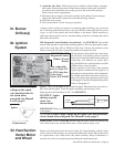
Instructions to Re-Install the Burner (Refer to FIGURE 23.)
1. Attach the Burner Assembly - Holding the venturi tube, slide the entire burner
assembly into position. Align the supports on the bottom with the slots in the
burner shield; sliding the supports into the slots. On the top, re-attach each
burner body support to the burner shield.
Re-Install the Burner
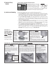
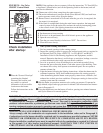
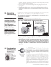
With the burner assembly removed, shine a flashlight on the burner ribbons. Look for
carbon buildup, scale, dust, lint, and/or anything that might restrict flow through the
spaces between the burner ribbons. Holding the burner assembly so that any foreign
material will fall away from the burner, use a stiff bristle brush to loosen and remove
any foreign material(s). If the burner is excessively dirty, remove one of the burner
end caps. Remove the four screws that hold the end cap to the burner housing. Lightly
tap the end cap to remove it.
Clean all foreign material from the burner and venturi. After the burner is thoroughly
clean, replace the end cap making certain that it is tight against the burner housing.
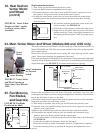
Inspect and Clean
the Burner
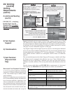
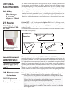
Inspect the Lower Portion
of the Heat Exchanger
(with burner assembly
removed)
At the burner flame entrance of each tube, shine a bright light into each heat ex-
changer section. With the light shining into the heat exchanger, observe the outside
for visible light. Repeat this procedure with each heat exchanger section. If any light
is observed, replace the heat exchanger.
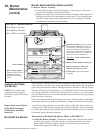
6. Remove Burner Assembly
a) Locate the three upper burner body supports. At each support, remove the
one screw that attaches it to the burner shield.
b) Holding the venturi tube, slide the entire burner assembly slightly upward to
disengage the burner from the supports on the bottom. Then rotate the open
end of the venturi tube outward toward the access door opening. Carefully
pull the burner assembly out of the cabinet.
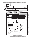
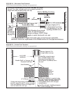
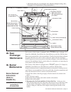
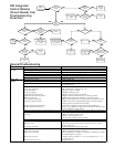
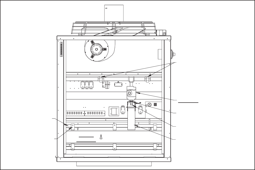
Burner Removal Instructions (cont’d)
Disconnect union(s). (On Size 400 or
the most downstream heat section in
a Size 800 or 1200, there will be one
union to disconnect. The first heat
section in Sizes 800 and 1200 and the
second heat section in Size 1200 will
have two unions to disconnect.)
Gas Valve - Mark and disconnect
the wires.
Remove orifice adapter locking nut.
Remove the burner orifice and
slide out through the bracket.
Venturi Tube (part of the burner
assembly)
Burner
Assembly
To remove burner assembly,
lift and rotate outward.
Burner Shield
Burner Body Support -
Remove the three screws
attaching the burner
assembly to the burner
shield.
FIGURE 23 - Burner Removal
• Size 400 has 1 burner.
• Size 800 has 2 burners.
• Size 1200 has 3 burners.
NOTE: If any of the burner
components are damaged or
deteriorated, replace the burner
assembly.
30. Burner
Maintenance
(cont’d)