


Form RZ-NA-I-LDAP, P/N 207733 (Rev 2), Page 11
Valve Outlet or
Orifice Pressure
Setting
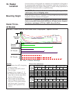
Measuring valve outlet gas pressure cannot be done until the heater is in operation. It
is included in the steps of the "Check-Test-Start" procedure in Paragraph 25. The
following warnings and instructions apply. Model LDAP 400 has one gas valve;
Model LDAP 800 has two gas valves; and Model LDAP 1200 has three gas valves.
WARNING: Valve outlet
gas pressure must never
exceed 3.5" w.c. for
natural gas and 10" w.c.
for propane gas.
For Natural Gas: When the heater leaves the factory, the combination gas valve(s)
is set so that the valve outlet gas pressure for a single stage valve or high fire of a two
stage valve is regulated to 3.5" w.c. Low fire on a two-stage valve (Size 400 only) is
set to 1.8” w.c. Inlet supply pressure to the heater for natural gas must be a minimum
of 5" w.c. or as noted on the rating plate and a maximum of 14" w.c.
For Propane Gas: When the heater leaves the factory, the combination gas valve(s)
is set so that the valve outlet gas pressure for a single stage valve or high fire of a two
stage valve is regulated to 10" w.c. Low fire on a two-stage valve (Size 400 only) is
set to 5.0” w.c. Inlet supply pressure to the heater for propane gas must be a mini-
mum of 11" w.c. and a maximum of 14" w.c.
Before attempting to measure or adjust valve outlet gas pressure, the inlet
supply pressure must be within the specified range both when the heater is in opera-
tion and on standby. Incorrect inlet pressure could cause excessive valve outlet gas
pressure immediately or at some future time. If natural gas supply pressure is too
high, install a regulator in the supply line before it reaches the heater. If natural gas
supply pressure is too low, contact your gas supplier.
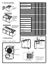
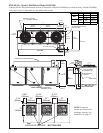
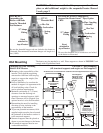
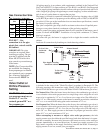
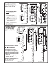
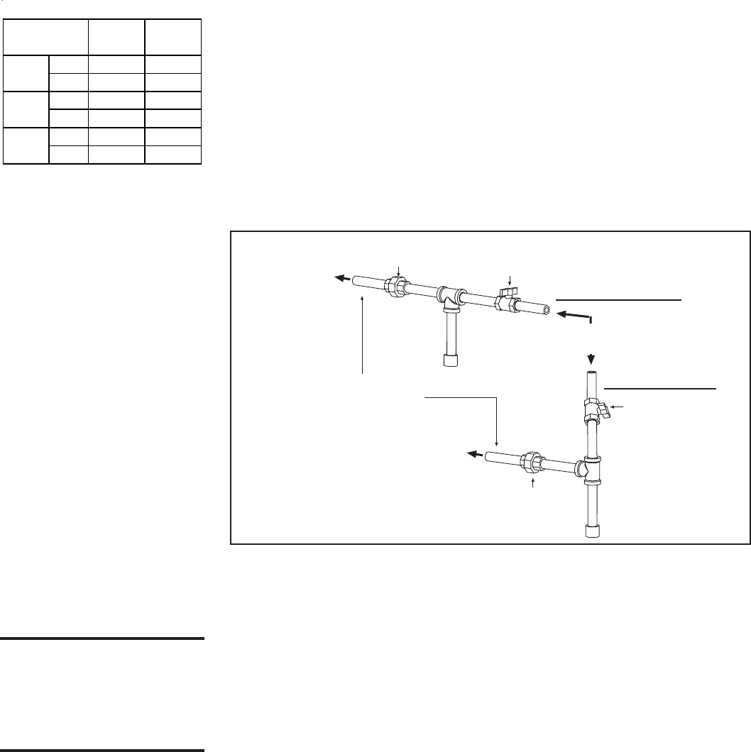
FIGURE 7 - Gas
connection is at the pipe
nipple that extends outside
the cabinet.
IMPORTANT: Two pipe
wrenches are required when
installing gas piping. The gas
pipe that is supplied with the
heater MUST be held with a
pipe wrench to prevent damage
to the heater.
From Gas Supply
(horizontal or vertical)
Manual
shutoff
Pipe nipple extending
outside the cabinet.
Drip
Leg
To Gas Valve
(inside the
cabinet)
To Gas Valve
(inside the
cabinet)
Ground
Joint
Union
Drip
Leg
Ground
Joint Union
Manual shutoff
Horizontal Supply
Vertical Supply
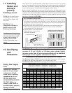
Gas Connection Size
All piping must be in accordance with requirements outlined in the National Fuel
Gas Code ANSI/Z223.1a (latest edition) or CSA-B149.1 and B149.2 (See Paragraph
2). Gas supply piping installation should conform with good practice and with local
codes. Support gas piping with pipe hangers, metal strapping, or other suitable mate-
rial; do not rely on the heater to support the gas pipe.
The heater is orificed for operation with natural gas having a heating value of 1000
(± 50) BTUH per cubic ft or propane gas with a heating value of 2500 (± 100) BTUH
per cubic ft. If the gas at the installation does not meet these specifications, consult
the factory for proper orificing.
Pipe joint compounds (pipe dope) shall be resistant to the action of liquefied petro-
leum gas or any other chemical constituents of the gas being supplied.
Install a ground joint union and manual shutoff valve upstream of the heater control
system, as shown in FIGURE 7. Installation of a trap with a minimum 3" (76mm)
drip leg is required.
To connect the gas, the heater is equipped with a nipple that extends outside the
cabinet.
Leak-test all connections by brushing on a leak-detecting solution.
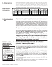
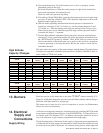
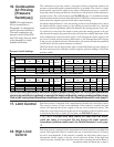
Gas Connection - inches/mm
Natural
Ga s
Propane
Ga s
inches
11
mm
25.4 25.4
inches
1-1/4 1-1/4
mm
31.8 31.8
inches
1-1/4 1-1/4
mm
31.8 31.8
Size
400
800
1200
NOTE: Gas Conversion Kits
are available for changing
from propane gas to natural
gas or natural gas to propane
gas. A factory-authorized
conversion kit MUST be
used.